DC braking with a soft-starter of a wood chipper

Jeff23spl

Member
Join Date
Jan 2010
Location
Canada
Posts
860
Hello all i know it isn't a plc question but with time i have seen a lot of knowledge here on motors/drive etc..

When braking with a drive, we can have an idea of possible braking torque but what about when we brake with DC injection on 2 phases VS the same + adding a shorting contactor on the third phase to use the regenerated energy?

Is there a rule of thumb of a ratio from motor nominal torque we can use as braking torque to estimate how much time it could take to stop, base of load inertia?

What i have found so far is more about emergency braking but in my case ( a wood chipper) i don't want instant stop (that would destroy everything) but just, reducing the time it takes to stop for knife replacement.
I wonder if i need to add the shorting contactor or just dc injection on 2 phases would be enough to reduce from: Let say about 25-30min coasting down on it's own to, less than 5 minutes....
 
I have never heard of a shorting contactor on an ac motor for braking
I donÂ’t see how that would work at all, that third phase would push energy back into the motor as the speed slipped below base speed making braking harder.
I have seen contactors in the motor lines to disconnect the power / VFD and switch in the DC injection braking.
DC injection braking will generally produce 33% motor torque at base speed and will reduce as the speed goes down and someplace just above zero speed it produces zero braking torque so it will never be able to hold position
I think the shorting contactor thing is from the DC motor days I know years ago they would short the armature (A1-A2) with a contactor to provide higher braking torque and shorter braking time. But the big disadvantage if not done carefully it can damage the motor. The same as they would open the field of a DC motor to over speed the motor at no load but if they were not careful it would blow up the motor


Agree with @Gary on 33%-ish torque for DC injection.


I have heard of shorting bars on DC motors (not recommended above maybe 5 HP) but not on AC. But I have not used a soft start for many years - it may be a recent thing.


30 years ago, we used DC injection to stop the Hog (big machine that chews up bark and various refuse into small pieces for burning in the boiler ... maybe it is still called that?) ... very high inertia load, the soft start took forever to start it (5 minutes maybe?) and it took 30+ minutes to coast down. DC injection was used at rated current on 2 phases and it took 10+ minutes to stop. That was 'normal stop' ... IIRC .. the cutting deck operator could select normal stop or fast stop. Fast stop was 1.5x rated current (I think .. under 2X anyway) but it would not let him start the hog again for an hour so it could cool down.
 
I worked on a large belt sander before, the manufacturer was Timesaver it had an electronic brake, the belt was about 70 inches wide and spun very fast not sure how many time per sec but very fast, with out the brake it would take maybe 5 minutes to spool down, with the brake it would take maybe 2 turns, but was adjustable

Not sure how it worked but definitely shorted something, maybe you can find out how there brake worked or buy and use it?
 
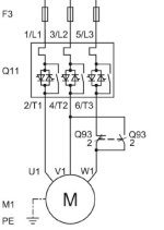
The Siemens manual isn't elaborating a lot but this addition is looking helpfull looking at the sizing of the contactor, they expect a lot of current flowing thru....(It use 3poles as a single one)

8.2.6.1 DC braking with external braking contactors
Operating principle
In the case of DC braking, coasting down or the natural stopping of the load is shortened by electrical braking using a brake contactor. The 3RW55 soft starter impresses a (pulsating) direct current in phases L1 and L2 on the motor stator. This current generates a permanent magnetic field in the stator. Since the rotor is still rotating due to its mass inertia, currents are induced in the short-circuited rotor winding that generate a DC braking torque. If the braking process is not completed on expiry of the stopping time, the motor coasts down.


33% with 100% FLA is close to what i found when searching around. I read at few places that it would need 2.5 time FLA to get 100% braking force on 2 phases.
But i didn't found much about results of shortiung the third phase...

third short.jpg
 
Last edited:
That's DC Injection Braking
in this case the soft start has the ability to do the braking
the pulsing makes me think they are just turning on one SCR on phase 1 and phase 2
why the Q93 contactor it looks like they are trying to pass the DC current through all 3 motor phases
they must have a miss print ( direct current in phases L1 and L2)
L1 and L2 are the line side i think they mean U1 and V1 on the motor
but the 33% braking torque is standard and braking torque reduces as the motor speed slows down

I agree that they mean U1 and V1.

For contactor #93 is said when we use the second mode of braking.
The first one is injecting on U1-V1 and they say it is when the load inertia is less than 1 time motor inertia.
The second mode have the contactor addition with the coil controlled by the SST. It is said for larger load up to 5time the motor....

I think it would be above 5times but i have to revisit my physic lessons and get more details from customer to be sure...
I did also ask Siemens to get more details about results difference when using each modes...Will comment if i get it.
 
I would like to see a detailed epilation of the contactor use in braking
the only thing I see is with the contactor closed the DC braking current could pas through all 3 motor windings as opposed to the 2 normally used but that would only a small amount of additional braking torque hardly worth the cost.
you can not dynamically brake an AC motor it requires an active magnetic field as with DC injection or as with DC motor the field provides the field
if they need to stop the motor quicker then with DC injection then you need to look at regen VFD's, with them you can do 100% torque and braking in the same time as the acceleration
 
Some older DC Injection Braking units (Ambitech Short-Stop, as I recall) had a shorting contactor, which shorted the motor phases for a short period to collapse the field, then they started the DC through 2 windings.

Some of the Soft Starters use all 3 phases for the DC, so as to distribute the heat more evenly...

You can acheive 100% (or more) braking torque without a Regen Drive... It just take a 'Big-Ol' DB Resistor... If it glows, get a bigger unit! Not all VFD's are rated for extended DB duty, so YMMV.
 
on the older DC injection systems they were required to interlocked with the motor starter contactor so the only way to inject the DC was in the contactor was open and the brake contactor was closed.
i have to differ wit you the 100% braking torque thing
DB is a term used with the old DC Motors both series wound and shunt wound motor the resister was switched in across the armature leads A1-A2 it is called db(Dynamic Braking ) because all the energy comes from the motor as long as the field has power
for AC drives they just carried over the term DB but what some companies had done is correctly name it Buss Loader because that's what it dose it dumps the excess energy from the DC buss in the drive through the resister and yes you can get 100% braking torque but the drive must be capable of taking the energy from the motor and passing to the buss first that requires a Regenerative or Quadrant drive standard drives do not have that capability the newer regenerative drives pass the excess energy back into the supply line where it can be used by other motors with them you can control the deceleration time and also have 100% braking torque all the way down to 0 speed this is not available in DB or Dc injection with them as the speed drops so dose the braking torque so at very low speed you have very little braking torque
I almost forgot the collapsing field on an ac motor happens as the ac cycle passes through zero once every 8 ms hardly enough time to even pull in a contactor
 
Last edited:
DB on a DC motor is not the subject here, and yes, there is no (easy) way on a DC motor to get 100% torque all the way to a stop without a regen drive.

You need to understand how an AC regen drive works, to understand my point. It is 2 inverters tied together by a DC bus, one pointing to the motor and one pointing the line.

When an AC drive absorbs energy from the load, the DC bus voltage rises. This is generally due to an overhauling load, due to decel time and inertia, or another outside force, such as a strong draft in a fan wanting to spin the motor faster than it is being told to. Basically, if the motor is turning above the synchronous speed of the frequency its being fed, it is generating. So, for example, if it's being fed 60hz, and its a 1750 rpm motor (1800rpm synchronous), but spinning at 1825rpm, it's generating about 1/2 it's rated KW back to the line (or to a VFD if so connected). If its on a VFD, the VFD's DC bus is taking it all. Now it either must get rid of it, or trip on over voltage.

To get rid of excess DC bus voltage, there are 3 methods:
- Use a 'Shunt Regulator' (Transistor and Resistor)
- Use a Regerative Module (another Inverter pointed at the line)
- Share the DC bus with other drives (Common DC bus network)

In any case, the VFD does the torque and speed control work. The added device(s) just shed the excess energy.

And yes, there are many high quality 'Standard' drives which can perform this way. Regenerative AC Drives are not new. Fully rated braking drives are not new. Many 'lesser' drives require a separate DB module for dynamic braking. They are just cheap designs, IMO. They are HVAC drives re-rated for General Purpose applications, IMO.

Whether you agree with the way folks have designed their products or not does not change the fact of how they work. Granted, I do not like some designs, but I accept their reasoning for going that route, whether I agree with it or not. I just go a different direction if I don't like a product design. There is no sense arguing about a current product's basic design. All you can do is hope that your criticism makes it to the 'Wish List' for the next generation.
 
Where to start I would like to beet this around the block a while
But all that’s going to do raise tempers and that’s not what I am about

As for understanding AC drives I have been installing and servicing both AC and DC drives since before they were in popular use I started on Shunt wound DC motor systems the speed control was resister banks switched in series mounted on slate boards
I was doing factory service for 5 different drive companies
I actually installed the very first 4, flux vector vfd’s in the US shipped directly to my customer from the manufacture in Japan. There were still some bugs in the firmware had to get the engineers over to correct them.
So I would say I am fairly well versed on drives and drive systems. I could go on and on but we don’t have time for that and I don’t think you really care about that.
I have worked on DC motor controls before there were drives the first drives I worked on were tubes
I do try to keep up the new things as they come out.
You stated that there are 3 was to dump the excess energy in an ac motor to brake the motor.
Dumping the energy is the key to braking in all cases .
But there is another one that was just released for general use
The drive has no DC buss at all, the conversion is direct line to line it’s 100% Regan
No buss loader or (DB ) as you like to call them the energy is pushed back into the input line directly.

I have received many calls to look at system others have failed on.
I don’t like the term DB as used on AC drives as they don’t work the same and I have seen people confused with their operation. There are a lot of terms that are holdovers from many years ago and have don’t have the same meaning today as they did when first used. One of the ones that keep popping up is 2 phase, to me 2 phase is 4 wire system with no natural but its not used anymore, but it’s still in use in old systems not understanding the difference can get you in trouble
 
Dumping the energy is the key to braking in all cases .
But there is another one that was just released for general use
The drive has no DC buss at all, the conversion is direct line to line it’s 100% Regan
No buss loader or (DB ) as you like to call them the energy is pushed back into the input line directly.

It's still 2 inverters, still a DC 'section' between them. There is very little capacitance in the bus for filtering. Just because it's new to the Japanese, doesn't mean it's new. The Europeans have been doing it for years. It's a lower performance design, but still cool (and cheaper!).

Sounds like you agree with me (y)
 
Gene
There is NO dc section no caps no DC buss
direct input line to output
Regen is direct to the supply incoming supply line
i don't think this would be possible without the high speed processors we have today
 
I think you are referring to what’s called a “matrix inverter” technology. It’s promoted as “new”, but in fact is around 30 years old. All of the major drive mfrs investigated it and found that the detractors outweighed the benefits. Only one pursued it, because in order to investigate it they had to produce the specialized bidirectional IGBTs used in the technology, so having made that expense, they (I guess) needed to recoup their investment. The big benefit is that the technology is inherently capable of line regenerative braking. The main detractor however is that it cannot deliver full speed and torque control to the motor, it peaks out at 86% and although it can be simply bypassed to run at full speed, it means there is no speed control between 86-99.9% speed (without loss of torque). Most VFDs in fact operate in that speed range a lot, so this is a big problem. There are other detractors as well, including the fact that there is only one source in the world for that technology and those bidirectional IGBTs, so supply chain disruptions and spare parts availability are further risks.
 

Similar Topics

Let's say I have an inverter fed three phase induction motor drive where in the braking phase (when the motor operates in a generator mode) the...
Replies
2
Views
135
I need some clarifications from VFD experts. I have a project with a vibratory conveyor that must be stopped relatively quickly. Stopping is once...
Replies
2
Views
785
Hello all. I have a parts elevator in a very dirty environment. I have used VFD's a lot over the years but I have never had to have one with a...
Replies
11
Views
1,760
I haven't done many applications with braking resistors, but we just put one in for a customer on a 60HP application for a centrifuge. We're...
Replies
21
Views
6,375
Hi, have an issue with a Powerflex 70 that has been installed with braking resistors. The resistors are sitting at 200 degrees Celsius. The...
Replies
5
Views
983
Back
Top Bottom