Hello gentlemen,
This goes back a few months and have been wondering about it ever since. I had an overhead door (High speed rubber door similar to this one)that had issues with its circuit board and I had to run it till the supplier ordered and replaced the board.
The door is unbalanced and its weight is hadnled using a 2.5KW motor and a gear box.
I hooked up an Emerson commander SK to the motor, brake and push buttons and ignored pretty much everything else. Going up I could run the motor at any frequency I wanted and I think I used 50Hz but going down was a different issue.
From a full open posisition as it cloesed the door picked up speed and tripped the drive. The fastest I could run it without hooking up a braking resistor was 10-15 Hz. It ran that way for a few days till the board was replaced.
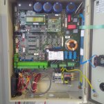
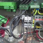
The question is, where's the braking resistor in this board (see attached image)? I am assuming there had to be one or how did they run the motor without it?
Cheers
Kal

Last edited:


