AD DL06 programming help

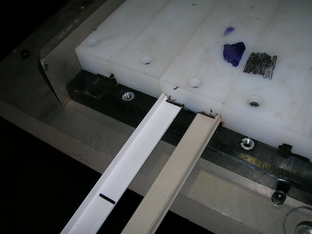
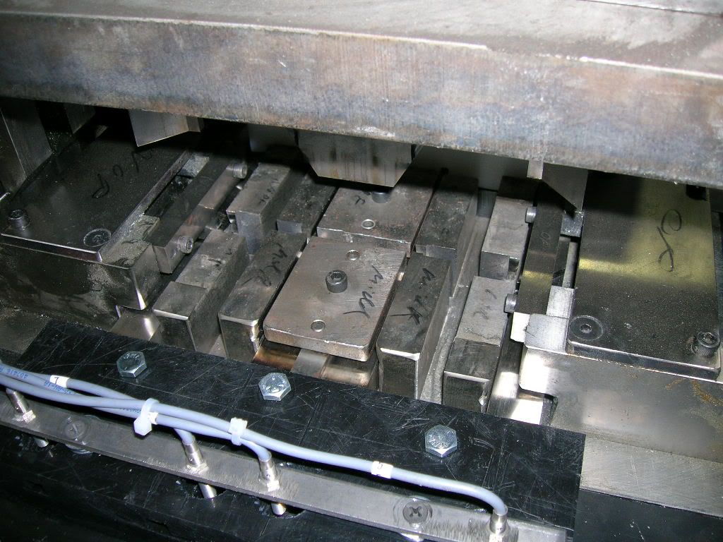
The material is an "L" shaped piece of PVC vinyl. It is about .051" thick, .770" wide, and the "L" leg is about .355" high. The raw piece is 18' long. It is the piece installed around the glass on a vinyl window. The punch we are using has 4 stations, 2 of which are used at the same time. Each "pair" of stations process the piece slightly different. The inner 2 stations cut the pieces at a straight 90 degrees. The outer 2 stations cut the pieces at a 45 degree angle and notch 1/8" from the "L" dogleg. They use all 4 peices on each window sash.
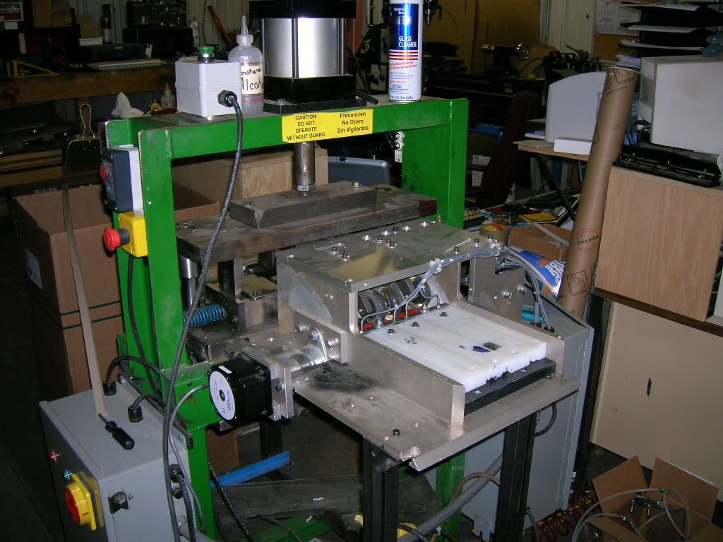
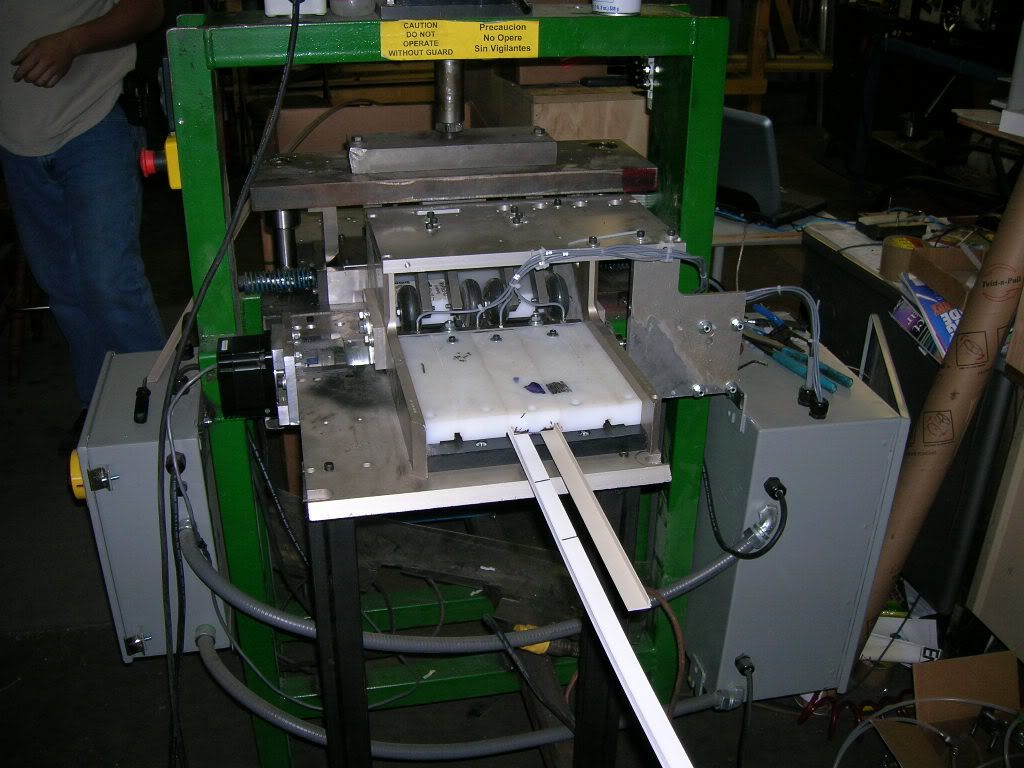
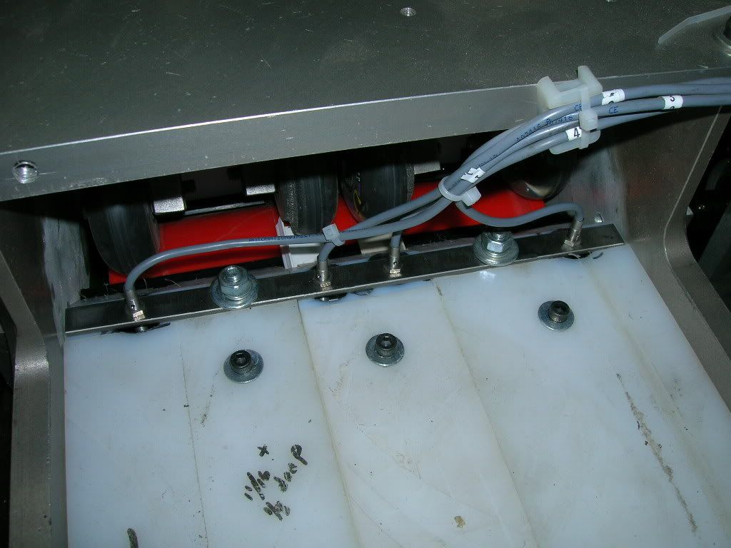
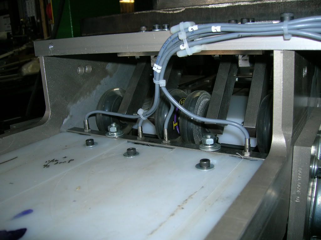
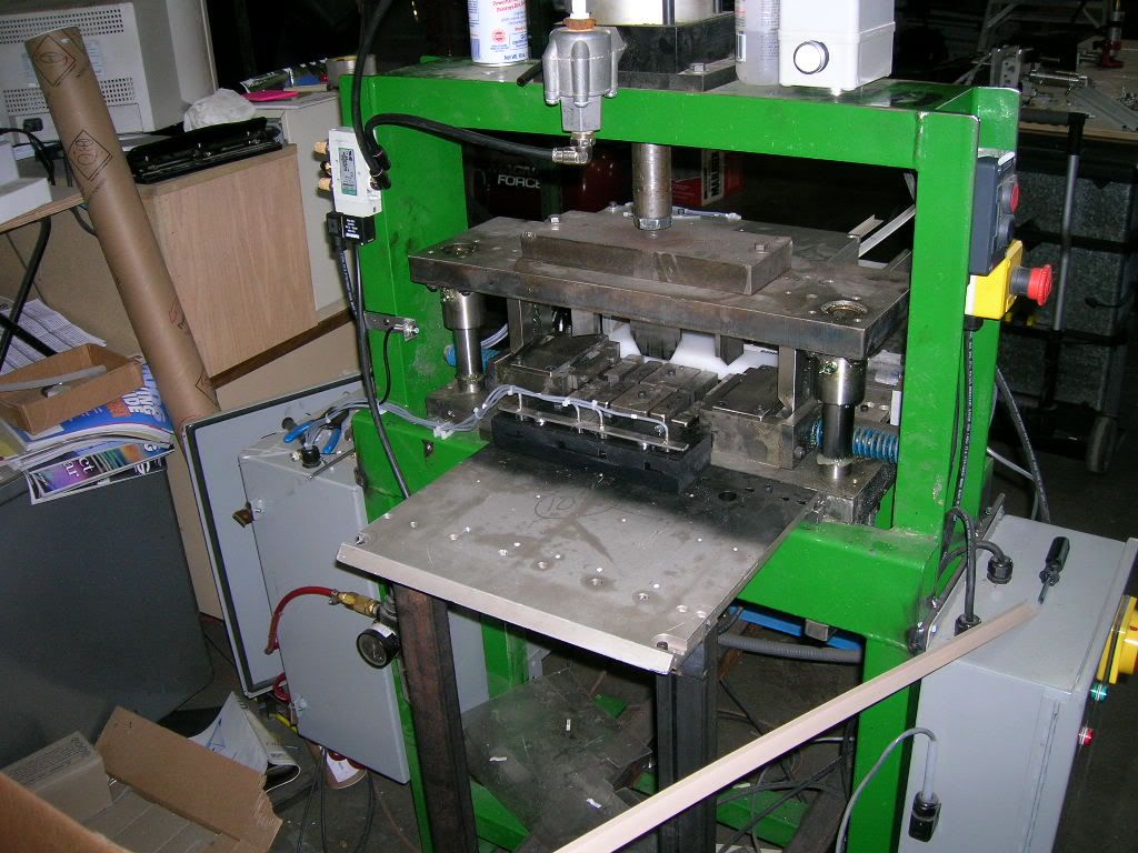
The punch was an existing unit in the plant that I am attempting to automate. I have a 3" polyurethane roller with polyurethane pinch wheels to feed the parts through the punch. I see the logic behind having the encoder mounted separately from the the drive roller. Do you think that mounting it to the pinch rollers is a good idea? There isn't alot of room for an extra roller in there. I currently have it mounted on the drive roller.
I'll try to take a couple of pictures today of the setup that we have to give you a better idea of what is going on.
I hope that my explainations are clear enough. I am not the best technical writer in the world.
 
Last edited:
photos of project: infeed & drive

Here are a few pictures of the project that I am working on. THe first photo shows that the encoder is attached to the drive roller. We are working on changing that.

rollers004.jpg


The next photo shows the infeed section with parts inserted. The sensors are there to only indicate when material in present.

rollers007.jpg


Here is a closeup of the drive roller assembly. yes,those are roller blade wheels for the pinch rollers.

rollers006.jpg


Here is anoyther view of the same:

rollers005.jpg


Here is a view of the material inerted in the infeed:

rollers008.jpg
 
photos of project: Punch & Outfeed

The first photo is of the punch and outfeed. Again, the sensors are for material sensing only.

rollers010.jpg


Here is a closer view of the punch assembly:

rollers009.jpg
 
I would reccomend mounting the feedback positioning encoder on a pinch roller set that is driven by the material, and not the drive rollers. The drive rollers will slip and you cant get around that, but the idler pinch rollers wont be so likley to slip, so that's where you want to get your feedback from.

I dont recall the details for the DL-06 right now, but the basic issue is you might want to use the same ramps for all lengths. How fast you go and the shape of the ramps etc.. depends on how much traction you have on your matierial.

I'm suffering from mental block right now and need to review mode 30 to give better detailed advice. So latter after work.

Post your program if you can.
 
I have hesitated to make any comments for several reasons. The first is this appears to be a MANUAL operation with speed not a relative concern, there has been no mention of a speed requirement.

If the above is true then you have definitely over-complicated the issue.

One factor I "assume" is that all material is the same length, therefore the PLC should always know what is left if there is material left in the machine i.e. if machine is turned off on Friday and restarted Monday then it should know what the length of the remaining piece is.....assuming each piece has the same length prior to being cut.

It is also possible to use sensors to determine an appoximate length and allow the process to cut if the infed material is long enough.

Since speed has not been stated as a concern AND this is a Servo system I do not think "slip" is a factor, if the operation is done at a low speed. A servo system can pass a setpoint then "reverse" and go back to the desired position...or within range.

Just my opinion but I think you need to step back into the box and make it feed and cut first then elaborate on that.
 
Speed is not a huge concern, It was connected to a Tiger stop before, and the parts fed through manually. Pretty much anything I do will speed things up.

Slippage is a concern. I have found that if the part is dirty or twisted or something like that it can slip a bit. One thing that one of my workers just thought of is that 99% of the time the operator will be cutting 2 pieces the same length... what if one slips and the other doesn't?

My thought to address this is to have the encoder mounted on a separate idler assembly and install sensors on the pinch wheels to verify the correct rotation, since they are already independent. Does this make sense?

I know now that I need to make some major changes to the code, I agree with rsdoran and make it feed and cut properly and then work out from there. Looks like I'll be busy for the next week or two.

Elevmike, I will post that code here as soon as I get the changes in it and documented properly. I am going to make the mechanical modifications and see where I how well I can get things working before imposing on you all again. Pstephens has given me a a good example on what a well thought out and planned program can look like. I'm embarrassed by what I have now. :oops:

Thank you all again for the advice and taking time to help me with this. I'll keep reading the posts and hope that I can help others here too with my experience.
Thanks!!

Mike
:site:
 
ThermoT said:
Slippage is a concern. I have found that if the part is dirty or twisted or something like that it can slip a bit. One thing that one of my workers just thought of is that 99% of the time the operator will be cutting 2 pieces the same length... what if one slips and the other doesn't?

My thought to address this is to have the encoder mounted on a separate idler assembly and install sensors on the pinch wheels to verify the correct rotation, since they are already independent. Does this make sense?

The quaduature encoder will allow you to verify correct rotation, speed, and position.

Let's say you have the unit setup to the material feeds 1st through the drive rollers, then the shear, then the pinch rollers w/encoder. As the material feeds into the machine the pinch rolllers will not rotate until the material hits them. So after the machine is built and ready to debug, just add code to compensate for the distance between the pinch rollers and the knife.

I know now that I need to make some major changes to the code, I agree with rsdoran and make it feed and cut properly and then work out from there. Looks like I'll be busy for the next week or two.

Elevmike, I will post that code here as soon as I get the changes in it and documented properly. I am going to make the mechanical modifications and see where I how well I can get things working before imposing on you all again. Pstephens has given me a a good example on what a well thought out and planned program can look like. I'm embarrassed by what I have now. :oops:

Dont be embarrassed. Remember the title of Paula's thread. Everybody's been there.
 
elevmike said:
The quaduature encoder will allow you to verify correct rotation, speed, and position.

Let's say you have the unit setup to the material feeds 1st through the drive rollers, then the shear, then the pinch rollers w/encoder. As the material feeds into the machine the pinch rolllers will not rotate until the material hits them. So after the machine is built and ready to debug, just add code to compensate for the distance between the pinch rollers and the knife.

elevmike; You just gave me an idea: I could use the oufeed sensors to verify if the pieces have slipped in relation to each other. If the corresponding outfeed sensors do not trip within a certain amount of time differential, say, 1 scan, then it could have a slippage alarm before the piece even cuts. That would save alot of recuts, because the parts usually slip on startup. I could go to a rubber roller, too. that would give me a little more traction over polyeurethane.

elevmike said:
Dont be embarrassed. Remember the title of Paula's thread. Everybody's been there.

I know..it's frustrating to me though how much I've had to relearn getting back into this end of the field. I must admit, though I'm having alot of fun doing it. I am going to get a small brick PLC and start teaching my sons some of this too, it will go along with the computer learing they are doing. That hopefully help me at work, too.
 
The cut length can vary by 32nds from 12" to 84" The accuracy needs to be + or - 1/64".
That`s quite a range.
elevmike; You just gave me an idea: I could use the oufeed sensors to verify if the pieces have slipped in relation to each other.
Her`s another thought to go along with Mikes. If slip really becomes a problem let these out board sensors help more. Say your going to cut a 12" piece have a sensor at 10"`s now when you call for a 12" piece in your program you know when you reach 10" so just measure the last 2" while ramping down. Same with 84" cut when 80" sensor is made measure the last 4". This might not work in your application, but we`ve used measuring logs where there was slip.
 
Ok so after looking at the pictures some, you have a drive roller then an idler roller pinching aganst the drive roller. You will definatly have slipping from the drive roller. Personally I would be concerned about the drive roller slipping and marking up the finished side of the material. I would have done it differently in that the drive would be two pinching drive rollers, and the pinching idlers would be a seperate set. That's just my 1st impression, and it may not mean much if the rollers can grip the material without marking it.

So it appears that you have 4 different cutting tracks, left miter, right miter, and two stright cuts. I presume that you plan to cut only one type of cut at a time (in a single run)?

Ok so place all the idlers on ONE rotating shaft. That shaft would be mounted on bearings pressed into two air or spring loaded swing arms. The rotating idler shaft would protrude through the side of the machine (one of the swing arms) and you would mount a small hollow shaft encoder on it and teather the encoder to the swing arm.

Let's say your material is 0.100" thick. The swing should stop so that the idler rollers are about say 0.0500" above the drive rollers when there is no stock in the machine. So when you push the stock in the machine the idlers wont start counting until it makes contact whith the idlers. You will need to make a few test runs and manually measure them to come up with the proper value to compensate for any missalignment. But if done properly, after a few test runs you will find that the compensation value will be constant. So you might not need the sensors at all.

From the looks of the material I would plan on using about 30lbs of downward force on the idler shaft.
 
Thanks for the advice, Mike. That makes alot of sense. I do not have a marking issue unless the material get stuck in the machine, and the drive roller slips on it for several seconds.
You are correct about the punch having four tracks, The outer two are for the miter and the inner two are for the straight cuts. They are only using 2 at a time. The operator usually cuts the straights for an entire batch, then the miters.
I like the idea of the dual drive rollers. I need to minimize slippage and that seems to me to be the best way. I'll need to cut grooves in the upper one but that shouldn't be a problem.
For the idler/encoder setup, do I need to have 2 rollers again in a pinching setup? I would assume so to reduce drag on the material. I am thinking that I will set the idler/encoder up before the drive rollers. It works out better for space reasons and that way I can get rid the infeed sensors. Is there a problem with this that I am not thinking of?

Thomas; That is a great idea but I don't think it will work in this setup. I really have alot of cut sizes I have to deal with and the range varies greatly. I could see where it would be excellent for lumber or log cutting, something where you process alot of the same size peices before changing. This machine may have to cut a 22 3/16" part, then cut a 72 1/2" part, then a 12 3/8" part, etc. It all depends how the batch is set up.

Looks like a have ALOT of rework to do mechanically. Unfortunately I have also run up against a deadline because orders are picking up and they need the punch out in production again. I will be pulling the feed assembly off it, setting it up on the bench again, and incorporating the modifications. It's really not so bad, I can do everthing on the bench except cutting the piece. It will take some of the pressure off of me.
 
For the idler/encoder setup, do I need to have 2 rollers again in a pinching setup? I would assume so to reduce drag on the material. I am thinking that I will set the idler/encoder up before the drive rollers. It works out better for space reasons and that way I can get rid the infeed sensors. Is there a problem with this that I am not thinking of?


The idler rollers would be two pinching rollers. One of the two rollers would be fixed and the other roller, (presumabley the top one) would be the pressure roller with the encoder attached to the roller shaft.

The pinching drive rollers would be set up in the same manner however the top and bottm drive rollers would be coupled (maybe with a set of small gears), so they counter rotate, so both drive rollers will push the material through the machine.

I dont think it would matter much how you place the drive and idler roller assemblies so long as they are spaced as closer then the min cut lenth. Dont forget to make everything slightly adjustable.


Another thing: If you place the miter and stright knifes all in line, the machine could be programmed to cut both miters on a single peice in one run without having to re-load it. This would provide for more accurate cutting, and a less operatator intervention. This would require a seperate action for each shear, but would really enhance the productivity of the machine.

Lets say you have to make 5 2'x3' windows. Simply tell the machine through an operator panel to cut 10 each 2' long with left and right miters and 10 each 3' long with left and right miter, then walk away. A few minutes later all your peices are waiting for you in a bin.

You can also stack the material in an accumulator for an auto feed. In short it wouldnt be that diffucult to have the unit cut lots and lots of peices to order, with little operator intervention.
 
elevmike said:
Another thing: If you place the miter and stright knifes all in line, the machine could be programmed to cut both miters on a single peice in one run without having to re-load it. This would provide for more accurate cutting, and a less operatator intervention. This would require a seperate action for each shear, but would really enhance the productivity of the machine.

That is a great idea, but it's not that easy. Most of our windows are custom order, so the size varies greatly. We only run amounts of same size windows on commercial and stock orders, and the stock orders are usually run in the winter. The punches are in line, and it is feasible to cut all four pieces at once. The shears are actuated by one cylinder, also. So, every time I cut the straights, I would also be cutting the miters. It would take two separate drives and encoders because the windows are rarely perfectly square. I'll have to look into the cost of doing that. I wonder if it would be worth while to have separate encoders for each piece? Could the DL06 handle four encoders?

elevmike said:
You can also stack the material in an accumulator for an auto feed. In short it wouldnt be that diffucult to have the unit cut lots and lots of peices to order, with little operator intervention.

This also is a great idea but it would be difficult as these this material is flimsy and is sometimes twisted and bowed. Our supplier says that due to the small size and thickness of the piece. I think that it would be difficult to have an auto feed, given the variables. Did I also mention that I have three different colors to work with, too?
 
The punches are not inline with the same track. It seems that the material will have to pass through one track for a right miter, then be reloaded and passed again for a left miter. I'm suggesting that one pass would cut both miters if the thre miter shears were orintated along the same track.

The machine would feed and cut the top miter, then contunue feed, stop and cut the bottom miter (or strieight cut), etc.. This would only requre one track for cutting the material, but would requre a seperate air cylinder for each knife.

In my expierance, there is always a way to autofeed material such as this. It might not seem so easy, but if I had a sample of the stock I'm 99.9% sure that we could design an autofeed system for it. Plyability, length and warpage does not necessarly preclude the ability to oriantate and feed the material from an accumulator of some sort.
 

Similar Topics

Hi, Mostly AB guy here with a little Koyo experience, but all of its digital. I get handed three analog I/O cards and asked to prove that they...
Replies
6
Views
499
Hey everyone, Working on a system with a Koyo DL06 processor and it's my first experience with them. I have DirectSoft 6 and we got the program...
Replies
5
Views
2,335
Hi, I am a complete newbie when it comes to PLC programming and would love some help. I am trying to configure a machine consisting of a DL-06 plc...
Replies
2
Views
1,661
Hi all, I am making a test rig to be able to wire in any DL06 (or DL05) And create a HMI in red lions crimson 3.1 to test all the inputs and...
Replies
4
Views
931
I have a Cmore screen which is communicating to the DL06 in BCD and need to create a timer that works in real numbers for a test, I simply need to...
Replies
3
Views
2,137
Back
Top Bottom