Analog Vaule Stuck Detection Logic

Fitz

Member
Join Date
Aug 2005
Location
In front of my laptop
Posts
92
Anyone have a good example of logic to capture an analog value getting stuck/frozen/not updating (choose your terminology)? I have logic in place to store a value and then compare for a match after a delay. Problem is that it results in false alarms due to random matches happening, and not due to a truly frozen value.


Since the values I am working with are very small, I multiply the value to reduce the likelihood of a random match, but they still happen.


My next plan is to add more logic to prove the value is not changing after multiple comparisons.


I searched here and the net without finding anything useful, but the search terms are possibly too vague.
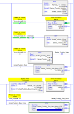
vmware_E4fqps3aLg.png
 
MOV block moving incoming value into stored value. Tmr to delay the next move.
EQU block comparing a stored and incoming value, if they match start a timer.
If timer hits DN. you have a data fault.

Your multiplying is having no effect upon what your doing.
1849.48585 is no different than 184948585 when compared against itself, only when a digit changes will there by a effective change for a comparison. the decimal place is moot. what you'll need to do is timers to delay the write to change the stored value and then compare against the live.

Are you by the process function going to see a change in 1-5 seconds? Your timer to update the stored should work within that timer period, then have a second timer start when the values store and live are the same. Timer should be long enough to determine you are not updating but not excessively so. 2 update cycles would work. Timing of course depends on your process entirely
 
Last edited:
MOV block moving incoming value into stored value.
EQU block comparing a stored and incoming value, if they match start a timer.
If timer hits DN. you have a comm fault.


Makes sense. Delay after seeing a match to see if it remains unchanged. (y)


Another thought I have is to store snapshots of the value into an array to capture consistent matching.
 
Just to clarify, the comparison (EQU block) needs to happen earlier in the program than the MOV block. Think of the incoming value as the value from the analog module at the beginning of the current program scan. The stored value is the value from the analog module at the end of the previous program scan.
 
How do you differentiate between a "stuck" value and a value that is not changing due to the process?
 
How do you differentiate between a "stuck" value and a value that is not changing due to the process?


There's the rub, eh?


If the process uses a sensor with enough resolution then there will (usually?) be noise in the data. That does not provide a way to differentiate, rather it makes the probability of the latter acceptably small i.e. small enough to be ignored.


If the sensor resolution is not small enough (I could see this happening on a level indicator, for example), perhaps noise, or an analog for same, can be added e.g. a timestamp or other counter from the sensor device. Of course, this is a pie-in-the-sky idea, especially in an existing process.
 
Makes sense. Delay after seeing a match to see if it remains unchanged. (y)


More specifically: delay as long as there is a match.


E.g.


Code:
---[EQU             ]---[TON   EN]---
   [SourceA  Current]   [      DN]---  [COLOR=Blue][I][B]<== this is the "it's stuck" alarm[/B][/I][/COLOR]
   [SourceB  History]   [Pre  ...]
                        [Acc  ...]

 TON.EN
---] [---[MOV            ]---
         [Source  Current]
         [Dest    History]
The [XIC TON.EN] feeding the MOV is not strictly necessary.
 
Thanks to all for the input. I'm glad I brought this up "for review", as I was asked to come up with something on the fly the other day without much time to think it through.


The inputs are from turbidimeters, and the values do typically fluctuate a bit as normal. A turbidimeter failed recently, with a steady output, so alarms were suggested to notify operators if it happened again in the future.


I'll make changes per these suggestions. Thanks again, and happy Thanksgiving.
 
I've tried this before with little success. The issue I had was that the analog input, if sensitive enough, will still see noise on the input even if an output device is stuck. So you would have to make a deadband or lower the resolution, which increases the likelihood of a detecting a stuck value that isn't really stuck. Which leads you to making the timer really really long.
 
Is this value something you have control over? I tend to put in place "movement without control" and "control without movement" alarms to catch situation like this... although a lot of times there's nothing you can do with whatever affects this sensor.
 
Most people just use analog input module status data to check if a channel is still functioning correctly.
 
Fitz - what brand turbidimeter? Most have reasonable diagnostics these days and can detect failed light sources, drift, no flow etc.

The Hach TU5300sc with a sc200 transmitter can be configured to give you a relay output indicating instrument trouble.

However, even that isn't infallible. The only real way to know is to use double validation using two instruments (there is a problem with one.. but which one) or triple validation (you know which one now, but you're also broke from buying 3 instruments for every monitoring point).
 
In the past i have used standard deviation on a value. You sorta have to tune the alarm value depending on how much noise you realistically expect. If the standard deviation drops below some value for some time, alarm.
 

Similar Topics

I'm having trouble calming down 2 Tempo Sonics. I'm using Studio 5000 CompactLogix my Raw value is jumping around from 8575.0 to 8755.0 at a...
Replies
9
Views
144
I cannot add SLC500 analog input tag (I: 8.3) to EZSeries Touch Panel Editor (V 5.3). I used all the listed tag datatype but it all says "Invalid...
Replies
8
Views
150
Hi, I have questions. I have Analog Input that need to put into Ignition Designer. But I don't know how to put?
Replies
1
Views
76
Omron AD081-V1 Analog Input Card Offset & Gain Adjustment Entering Adjustment Mode 1. Set the input card in adjustment mode (Turn ON Dip SW No-1)...
Replies
0
Views
54
Why AMIo800 Analog input module's I/O LED is Lighting up Red? Checked module connections, 4-20ma wires etc but this light is continuously Lighting...
Replies
1
Views
75
Back
Top Bottom