You are using an out of date browser. It may not display this or other websites correctly.
You should upgrade or use an alternative browser.
You should upgrade or use an alternative browser.
could anyone help me how to solve this problem via rslogix? thank you
- Thread starter ufomec
- Start date
Steve Bailey
Lifetime Supporting Member + Moderator
Depends on how the physical stop button is wired.@drbitboy rung 0 stop would be a XIC
In the US it's typical to use NC contacts on a stop button. If that is the case when you're not pressing the stop button the XIC addressed to that device evaluates as true, so rung 0 should be an XIC. If the stop button is wired using a NO contact, then the XIO instruction is correct.
Last edited:
drbitboy
Lifetime Supporting Member
Thanks for the prompt feedback; I was able to update the image before editing was no longer possible.
Depends on how the physical stop button is wired.
Agreed.
NC stop buttons is the approach we use too. Although it's common to see machines from overseas arrive with N/O contacts on start and stop buttons.
My comment was more so just to have rungs 0 and 1 on @drbitboys examples equivalent.
drbitboy
Lifetime Supporting Member
My comment was more so just to have rungs 0 and 1 on @drbitboys examples equivalent.
Wait. I still don't have it right? Oh dear ...
I used [XIO STOP(I:0.0/0)] initially so I could do everything on the MicroLogix 1100 without playing with wires.
I tested it. Or so I thought. hahahaha.
Last edited:
drbitboy
Lifetime Supporting Member
@drbitboy I apologise, your code was equivalent the first time.
@chelton no need for apology. this is too funny.
Steve Bailey
Lifetime Supporting Member + Moderator
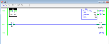
That gives the correct time delay before turning on the lamp.
drbitboy
Lifetime Supporting Member
guys. I thought for first step. Is it correct whren i push start button after 20 sec lamp it opened but i didn't continue second step.
Excellent! Well done: the light [O:0/0] turns on 20s after the input [I:0/0] becomes 1. This is a classic TON (Timer-driver ON-delay) circuit.
Also, the [OTL O:0/0] latches the light ON (assigns 1 to O:0/0), so when the timer is reset and [T4:0/DN] become 0, the light will stay on. That can be good too*, but at some point we will want the light to turn off as well, even though T4:0/DN may be 1. Also, if the input switch is turned off ([I:0/0] becomes 0) after 20s, then the timer will reset and [T4:0/DN] will become 0, but the light will say latched on. So there may be some more logic (instructions) added to Rung 0001 later to disable the latch [OTL] on every scan, and there will need to be a way for the light to turn off that looks at the input switch, but this is good for now.
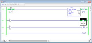
The next step is to reset the timer 20s after it starts timing, so it can start the next 20s cycle.
- What is the trigger to do that reset?
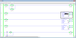
- Hints: what bit becomes 1 at 20s after the timer starts? You did something similar on Rung 0004 of Post #7
* The light could also be turned on, and kept on, with an [OTE O:0/0] fed by rungs that contain additional logic, instead of the OTL triggered by [T4:0/DN]. Sometimes an OTL is not preferred: for example if the PLC lost power, then the light would be on ([O:0/0] would be 1) when the power came back, and that might not be what was desired. But leave it as a latch for now.
Last edited:
drbitboy
Lifetime Supporting Member
Did you mean that for the second steps, but how is it going to turn off the latch in the transition to the last step?
Perfect!
Consider that the T4:0/DN Bit will behave like this:
Code:
Time ===>


T4:0/DN=1:            -           -           -
                     | |         | |         | |
T4:0/DN=0: --------- --------- --------- ---- ...Can you find a way to count those rising edges, and then use that count to inhibit the the timer, and turn off the light, after the third rising edge?
Hint: you will have to edit one, or more, of the existing rungs in such a way that it changes their behavior at the third 20s event, but does not change their behavior at the first [T4:0/DN]=0 event.
Last edited:
drbitboy
Lifetime Supporting Member
Also note that, with the current program, if the input switch is turned off between 20s and 60s, then the light will remain ON, because [O:0/0] was latched to 1.
So you will need some logic to turn off the light if [I:0/0] becomes 0. The timer will reset because the [I:0/0] controls the timer input rung, so you will not need to either do anything to the timer rung or add another reset.
So you will need some logic to turn off the light if [I:0/0] becomes 0. The timer will reset because the [I:0/0] controls the timer input rung, so you will not need to either do anything to the timer rung or add another reset.
drbitboy
Lifetime Supporting Member
Consider that the T4:0/DN Bit will behave like this:
So the T4:0/DN bit will be 1 for one scan every 20s; another way to say that is that T4:0/DN will have a rising edge every 20sCode:Time ===> T4:0/DN=1: - - - | | | | | | T4:0/DN=0: --------- --------- --------- ---- ...
And another way to say that is that T4:0/DN will have a false-to-true transition, although it would be better to say it will have a zero-to-one transition, every 20s.
I add this because the problem statement seems to come from a book's chapter 8 "Programming Counters" cf. https://sanamrao123.files.wordpress.com/2015/04/ch-8.pdf, and that phrase "false-to-true" is used fifteen times in that chapter.
Last edited:
Similar Topics
The ProSim-II Silo Simulation From the Simulations Menu at the top of the screen, Select the Silo Simulation
Exercise...
- Replies
- 9
- Views
- 5,891
I have an old PLC (circa 2007) consisting of Telemecanique/Modicon/Schneider Electric devices.
The system has developed errors and unfortunately...
- Replies
- 2
- Views
- 230
Hello,
I am trying to figure out how to create / write / delete a .csv file on the SD card of an Allen Bradley PLC.
There is a sample project...
- Replies
- 1
- Views
- 1,429
I have attached a picture. I just need to know if the option I've chosen is the correct one and if possible an explanation too. thanks
- Replies
- 14
- Views
- 3,649
Dear sir.
i have one Automation Direct hmi, if you have the CMORE Programming software,i will send you .eap file in email, can you please...
- Replies
- 3
- Views
- 2,439


