could anyone help me how to solve this problem via rslogix? thank you

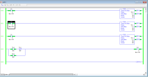
What are you trying to achieve with rung 0004? Using a timer's .EN bit is an unusual method of control. Most people choose to use the .DN bit. That's because the .DN bit reflects the time interval specified by the timer's .PRE parameter.
 
What do you expect rung 0004 is going to do? You already latched output O:0/0 on in rung 0000. There is nothing in your program that turns output O:0/0 off. Do you understand the difference between the OTL and the OTE instructions? The way you have constructed rung 0000 makes the use of the OTL instruction superfluous. And there is also the issue of using the same address for the output in rungs 0000 and 0004.
 
Last edited:
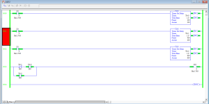
i did like this and it is working. It is correct and i need to use reset somewhere? I didn't understand this point.

Adsız.png
 
i did like this and it is working. It is correct and i need to use reset somewhere? I didn't understand this point.


Yes, because the intended solution has only one 20s timer, that repeats, not three separate counters.


Also, your solution does not solve the problem; the problem, from the book [Programmable Logic Controllers, by Frank D. Petruzella; see here and here], states
Write a program that will latch on a light 20 s after an input switch has been turned on. The timer will continue to cycle up to 20 s and reset itself until the input switch has been turned off. After the third time the timer has timed to 20 s, the light will be unlatched.
So the order of events should be

  • At 0s
    • the input switch is changed from 0 to 1
    • the output is 0 so the light is off
    • the timer starts its first 20s cycle
  • At 20s, the first time the timer completes its 20s cycle,
    • the output changes from 0 to 1, so the light turns on
    • the timer resets and starts its second 20s cycle
  • At 40s, the second time the timer completes its 20s cycle,
    • the time resets and starts its third 20s cycle
  • At 60s, the third time the timer completes its 20s cycle cycle,
    • the output changes from 0 to 1, so the light turns off
    • the timer resets and do not cycle any more.
However your program from post #35


  • turns the light on at 20s (good),
  • turns the light off at 40s (whoops!)
  • turns the light on at 60s (whoops!)
Here is how it behaves: https://www.youtube.com/watch?v=qdnLY8HxiBk


And here it is fixed: https://youtu.be/pWDY_jgC6MY


Note that, with multiple timers, the 40s timer is not needed.
 
@oziken:


Please perform the exercise suggested in post #11.


Also note that this problem, mentioned in the original post of this thread, is from chapter 8 (https://sanamrao123.files.wordpress.com/2015/04/ch-8.pdf) of [Programmable Logic Controllers by Petruzella], and the name of that chapter 8 is "Programming Counters." Since that exercise (#11 of chapter 8) is about counters, it seems that you should be using a counter in the solution. I recommend studying Figure 8-8 on page 152.


I would also recommend chapter 7 (https://sanamrao123.files.wordpress.com/2015/04/ch-7.pdf), called "Programming Timers," of the same book, especially Figure 7-11 at the bottom page 129.


Great detective work !

So teachers, tutors, lecturers, etc. don't set their own assignments ?

Could they even do them themselves without looking at the "answers" section.

Surely it is going to be extremely difficult to assess the student's performances, based on being told what a "good response" looks like.

Personally, I would confuse the hell out of the lecturer and put an SQO in there .... No timers, no counters, just a start/stop circuit and 2 other instructions, let him work that one out. .....

Perhaps I'm a bit like a friend I had (I'll reword that), A friend from a long time ago was anti-everything : paying-in slips with one corner cut off for automatic sorting, he would cut another corner off..... the machine readable fonts on cheques etc., he would get a pen and alter the characters to make them unreadable, he would stick a stamp on an envelope in the top-left corner, that sort of thing. That's the way he was ....
 
Last edited:
Personally, I would confuse the hell out of the lecturer and put an SQO in there .... No timers, no counters, just a start/stop circuit and 2 other instructions, let him work that one out. .....


Oh yeah, that SQO thing. Sweet!


My vocabulary is so limited in these languages.
 
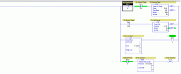
I believe this accomplishes what you are looking for.

I didn't use latches, but it works more or less the same.


You didn't use latches, when the original assignment specifically said "...latch on a light...", and "...the light will be unlatched.".

Also there is a problem with your code, in that the counter will continue to count every 20s if the input is left on, which means that just over 15 days later, the count will have cycled back to 1, then 2.

There are several ways to prevent this happening, perhaps the OP could suggest a way ....
 
I believe this accomplishes what you are looking for.

I didn't use latches, but it works more or less the same.


Nice. But Daba is right.


Also, from the problem description, turning off the input switch should always turn off the light, even if the counter is in mid-count (.ACC<=2), so I don't think we want the GRT instruction on the last line.


FYI, since this was an exercise and not a real problem, we were trying to get the OP to solve this mostly on their own, but with some guidance, not a turnkey solution.
 
Also, from the problem description, turning off the input switch should always turn off the light, .....

It actually does not say that. It specifically says that the latched light is unlatched "after the third time the timer has timed to 20 s"

No other mention of when the light goes off, so I say it should stay on indefinitely if the input is turned off to stop the timer timing.
 

Similar Topics

The ProSim-II Silo Simulation From the Simulations Menu at the top of the screen, Select the Silo Simulation Exercise...
Replies
9
Views
5,887
I have an old PLC (circa 2007) consisting of Telemecanique/Modicon/Schneider Electric devices. The system has developed errors and unfortunately...
Replies
2
Views
228
Hello, I am trying to figure out how to create / write / delete a .csv file on the SD card of an Allen Bradley PLC. There is a sample project...
Replies
1
Views
1,429
I have attached a picture. I just need to know if the option I've chosen is the correct one and if possible an explanation too. thanks
Replies
14
Views
3,646
Dear sir. i have one Automation Direct hmi, if you have the CMORE Programming software,i will send you .eap file in email, can you please...
Replies
3
Views
2,439
Back
Top Bottom