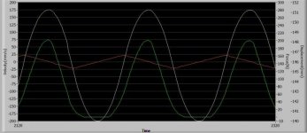
Don't want an "S" curve..need a cosine curve

So I have done wave tank applications using Delta Tau and LabVIEW. LabVIEW generates the positions every x distance and then I send the points to the controller to run(interpolating between points). Works very well, but you need a controller that can do that.

If you are talking about sine wave positional moves, the right values for accel, decel, and velocity is all you need. That can be done with a MC_Movexxx function block. I made a calculator that determines those values based on start position, end position, and frequency.
 
Since your needs are for position my pdf is useless.
My cosine ramps are for velocity.
I thought it would be which is why I didn't post it earlier.
Our old RMC100 used cosine ramps. The problem with cosine ramps is that the math is very messy if you want to change parameters on the fly while ramping up or down. The old RMC100 didn't have the power to do that. The RMC75 does but we decided to go with 5th order polynomials which approximate a sine wave sin(x) = x-x^3/3!+x^5/5! but the math is much more manageable and only differs from a sin(1) by less than 0.1%. You know we include real sine functions if a real sin function is required. My interest is in keeping unnecessary high frequency harmonics out of the target generator. A 5th order is 41 times better than a 3rd order at the sin(1).
 
I like it, quick and dirty but it should be good enough.

Highland, at least you make it clear what we are looking at. I assume the green line is force.

Since you are integrating a constantly accelerating velocity your sine waves are only parabolas or second order. That is probably good enough for Lamboom. Now the trick is for Lamboom to do the math to calculate how fast the acceleration must be to get the desired amplitude of motion.

Highland, did you do the math to calculate the distance or did you just use trial and error.
 
The problem is, I don't know enough ladder or ST programming to write the code that will control a working equation (4) shown above, that makes sine waves all day .. and have it just make 1/2 a curve cycle starting at zero and moving to a selected + amplitude in the correct time for the selected "period" of a sine wave. (cosine move ... :)

Even if you had a cosine function you'd need to phase shift it, cos(x) where x=0 gives you 1 (and not -1). sin(x+1.5*pi)+1 is what you want.

There is not one equation that does what you want (or maybe??). But you could find transactions between basically three stages. I did my own hack-n-slash version in ST (for an ABB AC800M controller) just for fun. Works as your curve there but without the drop before the ramp at the end.
 
Peter, although it is math, it is really simple math. Can't say that I fully understand 1st and 2nd order...

Lamboom, give me a distance to move and the time for that move, and I will give you accel, decel, and velocity for you to try in a MC_Movexxx function block.
 
Can't say that I fully understand 1st and 2nd order...
The order of a polynomial is the highest power of t or x in the polynomial.
for instance if pos(t)=a+b*t+c*t^2 the highest order is 2
if pos(t)=a+b*t+c*t^2+d*t^3 the highest order is 3.
Higher order polynomials are generally smoother because they can be differentiated more times. Most motion controllers use 3rd order polynomials.
 
You guys are awesome. I feel I'm talking to rocket scientists, and all I need is help lighting a match .. in the rain ... in the dark.

I already have a wonderful system, that works perfectly doing everything anyone could want in the making of waves for research or scientific demonstration in a wave tank. The Delta RMC75E does it all (along with a Red Lion HMI) Peter spent years yelling at me to go that route .. in the end, he always wins.

Why, you ask, am I messing around with an Omron system that isn't designed to do things like this ... well, I've already established that I'm an idiot .. so, it's not my fault. It just seemed like a fun thing to do, 'cause a friend didn't like Omron and wanted to get rid of stuff he had ... cheap!

The Omron NJ does have a cool function block, MC_SyncMoveAbsolute ... you give it a position data stream... and most any EtherCAT slave drive will make it's servo motor follow that stream .. really, velocity and acceleration isn't a factor here. You just feed this thing position data every every 1.0ms, and it works (you see that LinMot slider doing the Random Sea in the YouTube video above)

I just need to create a position data stream that will follow that trace above. Pay no attention to the glitch .. that was just a plotting error .. and was a different system .. it just shows the "idea" of the move sequence: Cosine position ramp, then hold (the ocean just got deeper) .. after the Tsunami comes ashore and wipes out millions ... the wave generator slowly returns to initial position..

I'm just looking for the ST or Ladder logic to control the position equation.

something like:
1) FORangle:= -90 TO +90 DO
2) FCOS:=Amplitude * COS(DegToRad(angle)
3) CCOS:=FCOS + FCOS

4) //MC_SyncMoveAbsolute
5) TsunamiWave (
6) Axis:= MC_Axis000
7) Exicute:= TRUE
8) Position:= CCOS);
9) END_FOR;

Now the above code will not work .. it just serves as an example of how not to do it .. Because, Period is not involved, and it has to be.

This equation creates a sine position trace starting at zero, and goes + then - for a peak to peak of 2 * Amplitude:

1)
FSin:=(Amplitude * SIN( 2 * Pi * SinTime/Period);

But, how do I code this to start at -1 and move to +1 then hold?

Omron's Cosine instruction would start at +1 and move to -1 for a full cycle. Sin and Cos instructions output radians

Peter said earlier: "
Lamboom, i don't understand where there is a problem unless the Omron doesn't have a cosine move. If not use the cosine function to generate position every 10 ms and tell Omron to move to that position with move absolute commands. Make sure the accel and decel ramps are fairly fast."

Exactly .. The problem is me .. I'm trying to program the cosine move with math.. using ST logic ... I could use ladder.
Omron doesn't have a function block for what I need (like Delta) I have to make one. They have a Function (FUN) for Sin, Cos & Tan. the FUN for cosine produces a cosine in radians of an inputted REAL or LREAL number. Sure they do have CAM curve ability.. but, I don't believe the cam-curve can be changed easily by inputted variables(amplitude and period)

It feels like I'm almost there ... must rest the brain for a moment.

PS.. still not getting any eMail notices when someone posts to this thread.... sigh!
 
Even if you had a cosine function you'd need to phase shift it, cos(x) where x=0 gives you 1 (and not -1). sin(x+1.5*pi)+1 is what you want.

There is not one equation that does what you want (or maybe??). But you could find transactions between basically three stages. I did my own hack-n-slash version in ST (for an ABB AC800M controller) just for fun. Works as your curve there but without the drop before the ramp at the end.

Dear Dirt: Thank you much for actually making a program! .. I think I can easily convert it to Omron NJ (Sysmac Studio) programming .. and it can certainly be done in 3 stages .. Kinda thought that was necessary from the start. If you saw my video a few posts back.. you will see there is one more "problem" to solve .. the Rogue Wave... :)

Tune in later for the next thread, where I have to create waves that travel at different speeds down the tank, then come together and make one Big Wave.

Will spend some serious time reviewing your program.. Thanks again: Stage1_Out:= Amplitude*sin(Pi*(time_to_real( Stage1_Timer.ET)/(1000.0*Stage1_TimeFactor))+(Pi*1.5))+Amplitude; The learning process is much faster for me.. when I see how programs are written .. I'm not an Automation engineer .. And I'm not near anyone that could help.
But, fortunately, I'm not totally dim... :)

This Forum has always been great.. and surprisingly tolerant.

time_to_real output is in ms, therefore division by 1000
the Pi just before the time_to_real is there because of scaling, wanted to express a half period time in seconds using the Stage1_TimeFactor variable.

Bear in mind I'm not working with motion as the other guys. The controllers I program are definitely to slow for this, but the math works. :)

Looking forward to the next thread and next problem. Kind of reminds me of some high school physics labs which were fun!
 
Dirt
This is definitely high school, college and museum display of ocean wave phenomena. It's really all about modeling structures, floating and anchored solid, then subjecting the model to a real model ocean environment. There can be some serious issues with scaling laws in an ocean model, but if the interest is mostly gravity wave induced, floating-body motion or water behavior, it's a good representation of the real world.

1/50 scale is common in large ocean labs around the world. This Micro Ocean is rather useful when working in model scales near 1/200. Stability of floating structures, effects or mass distribution in floating models, breakwater design, wave energy conversion ... lot's of uses.

Math isn't new to me.. I've just forgotten much of it.. you've done a good job rebooting those memories. Thanks. Regards, Michael
 

Similar Topics

I have been reading everything I can find on the P_LLS the last 2 days but I am still having trouble understanding how the P_LLS swaps beyond 2...
Replies
9
Views
580
In OB1, I'm monitoring some values (first pic). The values are what I expect. At the same time, I'm monitoring the same values in the DB where...
Replies
1
Views
650
Maybe I am the last to know but Rockwell has put an EOL date on the 3 motion modules at the end of 2024 but maybe sooner. I know this will affect...
Replies
1
Views
962
On the laser displacement sensor now connected to my PLC, the manual says 4mA=643 and 20mA=64,877. However, I checked with a Fluke, injecting...
Replies
5
Views
888
I'm from a Mitsubishi Q-series background so excuse my ignorance. In Mitsubishi world, in my experience your Mbits (booleans) are just M1, M2...
Replies
20
Views
2,776
Back
Top Bottom