
Analog sensor connection
- Thread starter PL_c
- Start date


Similar Topics
Hi,
We have a bag in box machine with a few payoffs that unroll foil. The inverters are PowerFlex 525 and the tension rollers mechanism is...
Hi, I have a bit of PLC experience in Siemens and have unfortunately been blessed with working on Automation Studio and B&R which has been a big...
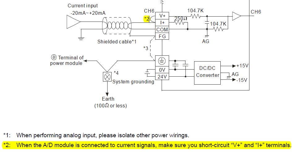
Hi,
I am working on a project with Delta PLC for the first time. I want to connect a Sinking analog sensor (4-20 mA) to a Delta analog module...
Curious, is it common to program in offsets to calibrate/correct analog sensor readings in certain applications? As an example, I have a couple...
I have a Bentley Nevada Velocity sensor that claims to spit out a 100 mv/IPS signal. I'm being told that it will work with an analog input card...