software and manual assistance

I have got an AOI that will convert hours minutes and seconds into a usable timer preset in the RSLogix 5000 platform, but you really need to know how AOI's work.

And it still depends on what HMI/SCADA you are using.

Mark
 
Sorry for delay in my reply and thanks for your response (y)

Time entered by the operator will be in minutes.( About HMI I will update shortly )

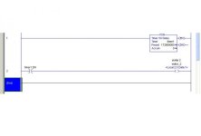
And the hour timer which I am asking about is seperate which will be in the program, preset for two days based upon which the two pumps should operate .(This is not part of the fan program I am just curious to know how to use a timer for two days 48 hours )

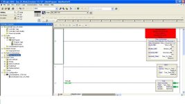
The jpg file is not clear and the .L5x file is not opening in my demo version .

Where can I find that time conversion function in Rslogix 5000
 
Last edited:
aec,

The L5K file is an Add On Instruction and needs to be imported not opened.

Go to AOI's right click and then import it.

Mark

That was awesome you are great (y). Actually I did not know or understand the use of AOI now I understand its use.

So any math’s function can be done by using this AOI isn’t it?????


From your calculation I see that the time is being converted to milliseconds

So for 5 sec I have to enter in timer preset as 5000ms am I correct.

So for two days can I enter as 172800000ms in the timer preset which is for 48 hours will it work?????

Reply when you find time .But I really appreciate your help. Thanks a lot.

Thanks to all the members of PLC.net who being in busy schedule try to help people like us .HATS OFF .
:site::site:

48hours.jpg
 
aec,

An AOI is not just for mathematical functions or purposes. I use it a lot when I have got a repetitive task, or lots of repetitive code to write, such as for valves and pumps etc.

I used to use FOR loops to do this, but I find AOI's are easier to follow. Do a search, there will be plenty of posts on here about AOI's.

All times in RSLogix are millisecond based.

If you have successfully imported the AOI I posted then put 48 hours into the hour box and see what it comes up with.

Mark

The problem is that I dont have a simulation, I only have demo version but by seeing the AOI I can understand how it will work .Thank you very much .(y)
 
Hi
I have no experience in analog so was reading threads related analog .Rather than just reading I thought let me do a example and learn .
I have my own basic idea to start with
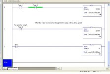
I have two float switches (float_1 & float_2) when the water level is at float_1 I should run the pump at half speed and when the water level reaches the float_2 then I should run the pump at full speed .
In general we use VFD ( variable frequency drive to control the speed of pump and we use 4-20 ma)
So I am assuming the VFD frequency as 0-50 hz
When at 25hz - half speed (pump)
At 50hz –full speed (pump)
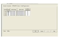
I am using analog Output card 1769-OF4 .
I searched for its Data format but could not find so I am using
(4-20ma) 0 to 32767 (Raw/ProportionalData)

Here I have doubt where should we use engineering units ?????

Considering all this I have done a logic .

When find time please give a look at the logic and give me feed back I am attaching.jpg file .
I also have attached .ACD file by converting it to .doc

Module configuration.jpg Analog practise.jpg
 

Attachments

  • Learning_analog.doc
    284.4 KB · Views: 10
Adding to the above post what other factor should I have to consider ?????

I should connect the analog output to the VFD analog input terminal (4-20 ma) am I correct . And to vary the speed of motor should I have to configure the VFD ??????
 
Hi all,
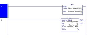
Ø Is it possible to move a value to the Sequence control .len ????????????
I am having Sequencer_Source[0],,,,,,,,,,,,,,,,,,,,, Sequencer_Source[6]
Since the sqo will omit Sequencer_Source[0] on the second cyclic I am using only [1]---[6]
How to avoid the time wasted on Sequencer_Source[0] in the first cycle ???????

Thank you .:site:

moving value to sqo.len.JPG
 
How to avoid the time wasted on Sequencer_Source[0] in the first cycle ???????
aec,


How much time is wasted? Maybe 1/10 of a second only when the SQO is reset ? Forget about it, in the entire working of the world, this is not a problem!
 
aec,

How much time is wasted? Maybe 1/10 of a second only when the SQO is reset ? Forget about it, in the entire working of the world, this is not a problem!

Hi Lancie1(y),

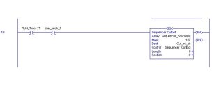
I am using timer to control the sqo . A fifteen minutes timer when the timer is running the Sqo will be energised and it should execute Sequencer_Source[1] for fifteen minutes then the timer will remain off for 15 minutes where the sqo should also be off, again after 15 min the timer will be on then sqo should execute Sequencer_Source[2] and this will continue till the value entered in Sequence control .len .

So at first cycle of sqo I want to neglect the first fifteen minutes spent on Sequencer_Source[0] .

And is it possible to move a value into the Sequence control .len ?????

Please correct me .:eek:

Thank you:site:

Using Timer.JPG
 
And is it possible to move a value into the Sequence control .len ?????
Yes, if you are careful! An error here can cause unpredictable results!

I think it would be smarter to move the Position. If Position = 0, then Move 1 to Position. This will skip over the Position 0. Then you do not have to worry about changing the Length. Notice that changing Len from 6 to 5 will NOT delete the Start Position 0.

You could skip Position 0 by adding a parallel branch on Rung 18, in parallel with the TT Timer contact, to check if Position = 0, and if true, then trigger SQO to move from Positon 0 to Position 1.

I would not use a TT timer bit to trigger the SQO. Notice that this only works when TT goes on for 15 minutes, then off. The SQO is only triggered when TT goes to OFF at the end of the 15 minutes. Normally a Timer DN bits works better. If the timer is self-resetting, DN is only ON for 1 PLC scan.

Another way to handle the Position 0 problem is to put a Comparison on the timer trigger, so that if System is in RUN mode, and SQO position = 0, then trigger 1 timer cycle (reset the timer 1 time), causing a skip of the SQO from Position 0 to Position 1.
 
Last edited:
Yes, if you are careful! An error here can cause unpredictable results!

I think it would be smarter to move the Position. If Position = 0, then Move 1 to Position. This will skip over the Position 0. Then you do not have to worry about changing the Length. Notice that changing Len from 6 to 5 will NOT delete the Start Position 0.

You could skip Position 0 by adding a parallel branch on Rung 18, in parallel with the TT Timer contact, to check if Position = 0, and if true, then trigger SQO to move from Positon 0 to Position 1.

I would not use a TT timer bit to trigger the SQO. Notice that this only works when TT goes on for 15 minutes, then off. The SQO is only triggered when TT goes to OFF at the end of the 15 minutes. Normally a Timer DN bits works better. If the timer is self-resetting, DN is only ON for 1 PLC scan.

Another way to handle the Position 0 problem is to put a Comparison on the timer trigger, so that if System is in RUN mode, and SQO position = 0, then trigger 1 timer cycle (reset the timer 1 time), causing a skip of the SQO from Position 0 to Position 1.

Thank you Lancie1:site: , sorry for the delay in my reply .
As you said I will use compare and move instruction .
 

Similar Topics

I am looking for leads on getting a manual in English for the Klockner Moeller VTP HMI software. The software is VTP and was DOS based. From what...
Replies
0
Views
552
dear all members: i need manual for dfm4win software and cable schematic to connecting pc to elektronikon.please if anyone have it send me or...
Replies
4
Views
4,476
Dear All, Recently we have problem with servo controller called AZ 20 (old AMK Servo controller). The program writen in software called APROS. I...
Replies
4
Views
3,744
Anybody able to point me in the right direction to get programming software/manuals for one of these? Eurotherm SSD LINK L5207-2-00. Thank, Jack
Replies
4
Views
2,433
We have a couple of instances in our control systems where we want to, for example, force a PID controlled motor to a minimum speed or force a...
Replies
4
Views
1,717
Back
Top Bottom