The Difference between ladder logic diagrams (LDR) and statement list (STL) in PLC ?

jimbojohn

Member
Join Date
Mar 2015
Location
Adelaide
Posts
7
Hi dear enthusiasts;),


I am taking a PLC course where we use Festo PLC (FC660). I did some LDR programming before and not until recently I thought that was the best way to program the PLC. I was recently introduced to STL which is a lot like assembly language and since then my confusion has been increasingo_O. What is the difference between LDR and STL, besides just the appearance? My teacher asked me to only put the tasks which can happen any time (or must be accounted for at any given time) in the LDR. He asked me to put the rest of the process stages in a sequential format in the STL. He told me the STL format takes care of the sequential stages not things which may happen at any stage (i.e. pressing a stop button any given time).
So, I am a bit confused now. What purpose do STL and LDR serve? Can I not just use one or do I have to use both in a program. I used to only use LDR as my course of study was only limited to it. Also I was told that LDR is also sequential and now I am told otherwise, I am told that it can take care of things that happen any time in the process. Now, I came across the term “quasi-parallel” or “pseudo-parallel” logic. How does that fit in LDR and STL working together and where does it come into play?
Any help and resources are appreciated:ROFLMAO:
 

Thanks for your reply.;)

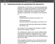
I did have a look at the manual that you linked before. It does not really say that LDR is for things that can happen any time. As far as I understand, one can prefer to select either LDR or STL to do their job. In other words, it appears to me that it is a choice based on one's convenience rather than functionality of LDR vs STL programs. As it says in the manual LDRs are also sequential and "quasi-parallel" processing really only works if there are not a lot of programs running, otherwise the delay may become sensible. But there was one sentence in there which may reflect what my teacher said about LDRs and how they are different from STLs on page 271:

In the STL program, only one step is executed at a time, whilethe LDR programs process until the end (unless they contain
jumps or program module calls).


But, I still can't see how this changes things? :unsure: Does not a parallel STL just act like a LDR then?:confused:

Many thanks in advanced;)
 
The STL program can be setup to operate in 3 different modes

Thanks for the reply!;)

I read that section too. Based on my understanding there is no necessity to use LDR really. Technically, one can use parallel STL and functionally achieve the same performance that one could if LDR was used. That was one of my questions in the last reply and I just wanted to confirm it:

Does not a parallel STL just act like a LDR then?:confused:

The only advantage (and distinction) of LDR over STL is its simplicity and diagrammatic form, otherwise one can achieve the same performance with a parallel STL (and please correct me if I am wrong:unsure:).
But sometimes one needs to have a stepwise operation in which the next step of a process will not be performed if the requirements of the current step have not been yet satisfied. This is when one has to use stepwise STL and can not use LDR. Because LDR executes a whole cycle continuously (Please correct me if I am wrong here too:unsure:).
 
There are many methods of programming a sequential/stepwise sequence in ladder as well.

The argument for LDR vs STL is a long and complex one - there's a few threads on the forum here and they run for many pages.

At the end of the day, you use what's best for you as the programmer/your company/the customer/the end user/the maintenance crew based on all the different pro's and con's of each language.
 
Ladder is easier to trouble shoot for electricians and the like. STL if the syntax is not right good luck. I have customers in remote locations and when they ring with an issue I can go through ladder with them to find their issue - cannot do that with STL. That is a simple explanation of why I use ladder - there are other reasons like I can write software much faster in ladder than STL with the programming software I use but that is another issue.
 
Cheers!

I see that the convenience of ladder logic diagram is the main reason that you prefer it rather than any functionality differences over STL.
 
Yes - saves me traveling for 2-3 days to sort out what is usually a simple problem. Also speed of software development means I finish a job quicker, get on to the next one quicker and make more money. Software development and commissioning can often mean making good money out of a job, breaking square or losing money. It can also stop one getting on to the next job in a hurry as well so double jeopardy. The quicker the better.
 
your teacher is correct, almost.
A ladder is scanned from top to bottom (when not using jumps)
I use it when safety is needed.
As it scans all the rungs allways.

In Statement list it is easier to make calculations, and call to other programs or function blocks

There is also a seqeunce editor in (codesys) called SFC.
and a CFC for complex things (sort of matlab)
and when you want bits also IL.
 

Similar Topics

Hello, I have a problem with AO- and AA-Tags. When I use for example the tag AO_Test with the address 200 and type the value 1,2 in, the AA-Tag...
Replies
7
Views
1,406
As per the title. This might seem like a basic question to many, but I'm unclear about the difference between a coil ( ) and an application...
Replies
28
Views
4,015
Good Morning , I have 2 Frequency Drive panels to build and commission . It is for 2 pump systems . Just wondering , what is the...
Replies
4
Views
1,960
Hi Experts, Good day! What are the differences between PCS7 SIMATIC Batch and PM Control? Do you have any manual like "Getting Started "...
Replies
0
Views
805
I have a Automation Direct Click Plus that you can buy option CPU slot modules for input/outputs. The slot modules have the options of sinking...
Replies
9
Views
2,809
Back
Top Bottom