Analog Input Module

dbh6

Lifetime Supporting Member
Join Date
Jan 2013
Location
Central, NJ
Posts
552
Hello all,

I so happen to be working with a program that has a AB 1756-IF6I, analog input module. I noticed that once you right click on the module in the IO configuration in the controller organizer and select properties it has couple of tabs, one of them which is the configuration tab that has input parameters for the scaling for the High/Low signals in ma and also the High/Low engineering values.

From the process that i'am working on, we have a lot of pressure transducers that are sending a 4-20ma signal as an input to the channels on the 1756-IF6I module.

So my question arises, since this module already has set point parameters for your scaling, would this omit the need to use scaling calculations in your logic? Ex. if you put 20ma as the high signal and 4 ma for the low signal and have high / low engineering scaled values of 100 & 0(representing PSI) would the 4-20ma signal correctly scale an output value between 0-100 PSI depending on what the 4-20 signal is?

Lastly their is an input range where you specify what kind of signal is coming in, in my case i selected the 0ma to 20ma as that is the only option for for a ma signal. So since 0ma to 20ma is the only option, then when you enter your scaling values for the High /Low signals should the low signal be 0ma or 4ma? because if i use 4ma then how will we be able to differentiate Ex. from a broken wire when the ma signals drops below 4ma? and if we choose 0ma as our low signal then our scaling won't work correctly because the pressure transducer is sending a 4-20 not 0-20, maybe play with the Sensor offset parameter???

If someone can clear this up, i would appreciate it, btw plc is a control logix with 1756 L62 CPU.
 
regarding your questions ...

since this module already has set point parameters for your scaling, would this omit the need to use scaling calculations in your logic?

yes, unless you needed an additional range for an operator's HMI display, etc. ...

if you put 20ma as the high signal and 4 ma for the low signal and have high / low engineering scaled values of 100 & 0(representing PSI) would the 4-20ma signal correctly scale an output value between 0-100 PSI depending on what the 4-20 signal is?

in the simplest terms, yes ...

So since 0ma to 20ma is the only option, then when you enter your scaling values for the High /Low signals should the low signal be 0ma or 4ma?

4.0 mA would be the better choice ... as you've obviously guessed, the 4.0 mA reading would correspond/equate-to/represent an actual field condition of 0 PSI ... 0.0 mA would NOT be accurate ...

if i use 4ma then how will we be able to differentiate Ex. from a broken wire when the ma signals drops below 4ma?

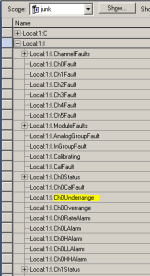
see the figure below ... you might also have your program logic test for an input reading which would be "Less Than" 0.0 ... specifically, in most cases the reading will go below the "minimum" if the field input signal goes below the "minimum" ... more specifically, you would expect to see a negative value in the reading by using the examples that you've mentioned ...

suggestion: get yourself a "test" system to play with (oops! I meant to say "work with") and try out some of these ideas yourself ... you're asking excellent questions ... you'd learn more - and discover new features - by experimenting with the ideas that you're bringing up ...

.

ch0underrange.PNG
 
Last edited:
Thanks Ron, for your quick reply, I had actually written my logic with scaling calculations errr!!!! now have to go back and change it, its ok though. I noted that you highlighted in yellow the CH0-Underrange so when the signal depending on how we configure the scaling, drops below 4ma that bit will be set, same would apply for the over range if it goes above 20. Lastly if you keep scrolling down their is a rolling time stamp tag, so you know what that is used for, or better yet what it is?? thanks in advance
 
One thing that you might want to consider is that, by scaling to Engineering Units at the module level, you are trading convenience for numerical granularity in the input data that you will be using within your PLC logic. This is especially important if you plan to do control with the input signal, rather than simply displaying values to the operator.
 
@ BitBucket07, I'am definitely using the input signal for control, what i originally did was, i took a cpecific channel data value (real format) then i used my scaling calculation in my plc then whatever the output was from the scaling, used that in my control logic. Now since the scaling is taken care of at the module level, i'll just map that data (at the begining of the scan routines) straight to the tag that i'm going to use for the control logic, that way i'll avoid any issue with the IO's asynchronous update issue that i may face if i had used the module's data tag directly to my control logic
 
from dbh6 ...

that way i'll avoid any issue with the IO's asynchronous update issue that i may face if i had used the module's data tag directly to my control logic

I think you're worried too much about that "asynchronous" scan thing ...

quick question: how many times will your program logic make use of the input signal? ...

(A) only once per scan cycle ...

(B) more than once per scan cycle ...

if the answer is (A) then you really don't need to worry about the asynchronous issue ...

think about it this way, if you buffer the input signal to prevent it from updating part way through the scan, what have you really gained? ... the simple answer (in the vast majority of cases) is "absolutely nothing" ...

my point is this ...

any new input value would get updated (into the buffer) on the very next scan anyway – and just a tiny fraction of a second later ... so when you look at it objectively, in most cases an update to an analog input signal PART WAY through a scan cycle isn't really going to upset the apple cart ...

exceptions DO exist – but they're rare – and they invariably involve situations where the program logic makes use of the input signal's value in multiple places throughout the same scan ...

going further:

the 30-year-old workhorse PLC-5 system has always used Block Transfer Read operations to move its analog signals from an analog input module into the processor's data tables ... those BTR instructions are actually executed "asynchronously" to the program scan ... even so, I don't think I've ever seen anyone bother to "buffer" those analog input signals – and life went merrily on ...

going even further:

with a ControlLogix system there is more to the updating of analog input signals than you probably realize ... when you've got some spare time (whatever that is) then it might be a good idea to read through this thread ...

http://www.plctalk.net/qanda/showthread.php?p=391975&postcount=1

I hope this helps ... my intention in writing it is to make this easier for you – not to make it more complicated ...

now I've got to get back to work ... good luck with your project ...
 
Last edited:
@Ron, thanks for taking your time to explain the whole "asynchronous topic", will definitely go through that link you provided on the RPI's etc.
 
One thing that you might want to consider is that, by scaling to Engineering Units at the module level, you are trading convenience for numerical granularity in the input data that you will be using within your PLC logic. This is especially important if you plan to do control with the input signal, rather than simply displaying values to the operator.

Not quite true - the scaling is done on the card to whatever engineering units you want as a REAL data-type. That is the best you could do in the code if you pulled in an integer value and scaled it yourself.

If there is any numerical granularity, then scaled in the card or in the controller, there'd be no difference - it will still be there.

Use the card scaling, it simplifies absolutely everything, and then you can do your HH, H, L, and LL, process alarms in the I/O module as well. And while you're there, you might like to try the Rate-of-Change alarm as well.

@dbh6 - the "0 to 20mA" range is just that - an input signal range.

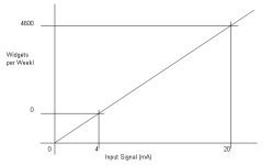
The scaling min and max can actually be anything you want - so if you are using a 4 to 20mA input signal to represent 0 to 4600 widgets per week, then it's easiest to put those 4 figures in the channel scaling.....

Signal Min. 4
Signal Max. 20
E.Units Min. 0
E.Units Max. 4600

The pic. shows the actual scaling that the module uses, and is the same as the SCP instruction does.

2013-03-27_163805.jpg
 

Similar Topics

Why AMIo800 Analog input module's I/O LED is Lighting up Red? Checked module connections, 4-20ma wires etc but this light is continuously Lighting...
Replies
1
Views
109
In this sample programming, what does U4 mean? Any assistance would be greatly appreciated.
Replies
8
Views
271
Dear Members; We have Fluke 754 hart communicator. We have wired up three transmitters of Rosemount Model C3051 with this input module. But when...
Replies
4
Views
1,840
Hello all, Thanks for the forum which has provided me with a lot of help overtime. I'm posting my first thread since I can't seem to find an...
Replies
4
Views
2,033
I am facing an issue module 1756-OF8 is showing the minor fault = recoverable in the module info.How can i reset it?
Replies
0
Views
1,758
Back
Top Bottom