Ladder Logic and Methane Detectors

djinak

Member
Join Date
Apr 2003
Location
Fairbanks, AK
Posts
8
I am having troubles getting my PLC to do what I want. Here is what I want to do...I have a facility with 4-20 mA methane detectors that are hooked up to a PLC and monitored by WonderWare on a PC. What I want to happen is:

1. At 25% LEL (1.25% methane to air)-->send an alarm to the PC and dial out messages with Viking autodialers
2. At 50% LEL (2.5% methane to air)-->ESD (emergency shutdown) some valves as well as send an alarm and dial out as above.

Currently, within the ladder logic, I have it programmed:
1. >/= 25% < 50% -----> Alarm and Dial out
2. >/= 50% ----------> ESD and Alarm and Dial out

This doesn't work the way I think it should. I am pretty confident in my values and programming. No matter what the methane detectors are reading, the PLC only acts as if there is 25% LEL. As methane levels rise, the PLC should ignor the 25%-50% levels and react to the >50% actions. It seems like the PLC gets stuck on the 25% LEL actions and never gets to react to the >50% level.

I'd appreciate any suggestions or just discuss with someone who has programmed something similar...Thanks
 
It would help if you could identify which entity is doing what in your system. Does the PLC ladder logic set internal flags at the 25% and 50% levels? Does the PLC ladder logic turn off the valves when the 50% level is reached?

Is Wonderware monitoring both the analog input data and the two flags. Who controls the trigger signal to the autodialer, PLC ladder or Wonderware?.

What brand of PLC? Can you post examples of your ladder logic?
 
Hi Steve. Thanks for the responding...OK answers to your ?s

1. I don't know what "flags" are
2. No, the PLC does not turn off the valves as programmed. I would like it to, but it only sends alarms as programmed.
3. WW is monitoring the inputs, but WW doesn't perform any actions. It does its own alarm from presets in the WW, but doesn't instruct the PLC to do anything. The WW is used only to monitor. The PLC should do its stuff even if the PC and WW were off, such as shutting down valves if 50% LEL were detected by the methane detectors.
4. The PLC triggers the alarms and the autodialers and routes the ins to the WW.
5. Its a Automation Direct PLC, DL 405, 450 PLC
6. I can post the portion of the ladder logic involving the gas detectors, but I don't know how to on a reply. I might have to do a new thread and post it then.

Thanks
Duncan
 
When I used the term 'flags', I meant internal coils. If the PLC is supposed to turn of the valves at the same time as it turns on the alarm, then it sounds like we need to debug your ladder logic. Look through the FAQ section here for advice on how to attach images or files to your post and how to post ladder logic.
 
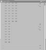
I am attaching the portion of the ladder logic that pertains to the methane detectors. Everything else works as it should, so I think this is all that has issues.

The values relate are converted from the mA input and stored in the PLC. The outputs are actions that should either alarm, or ESD valves, or both.
 
A couple of things I noticed:

First, for most of the DirectLogic analog I/O the data range is 0 to 4095. I don't know the full scale of the transmitters, but the constant you are using (K819) implies the transmitter signal is 20 mA at 125% LEL - is that correct?

Second, change your settings to show the nicknames and rung comments -it makes life easier.

Third, I prefer to use a register for full scale, and then convert the individual readings to engineering units - in your case I would use 1000 = 100% of LEL. There are other threads on the forum you can serach for to show how to get engineering units.

Fourth, I hate SET and RESET - particularly in this kind of logic. It makes performance hard to track, as you are finding out. I suggest you use an internal coil for each compare - that lets you see which sensor is the problem, and lets you latch the offending alarm until it is reset by Wonderware. Use these coils to trip your alarm output.

Here is my idea:

Code:
|  Sensor1          WW_Reset_Bit
|   V3000   K500       C700            Sensor1HiHi
|--------|>|-----+-------|/|-------------(C300)
|                |
|    Sensor1HiHi |
|------| |-------+
|
|
|    Sensor1HiHi                         AlarmOut
|------| |--------+------------------------(Y24)
|                 |
|    Sensor2HiHi  |
|-------| |-------+
|                 |
 
If you need to do an off-site test with your methane detection equipment, you could call here at my office this saturday.

After an excellent friday evening imbibiing alcohol and finishing with a curry that was just superb, I could give you an 100% reading for you methane detector. :D
 
To Tom's last response

Tom,
1. As I understand it, 4-20 mA as 0%-100% LEL, equates to K819 and K1638 as 20% and 40% of 4095. (I have been discussing 25% and 50%, but my ladder shows 20% and 40%...sorry). Is this not how it works? 0.2 x 4095 = K819?

2. Nicknames are now shown

3-4. We WW to monitor ONLY in case of the PC crashing. The PLC will still perform tasks needed then.
I understand the need for doing things the write way, but I am very lacking in knowledge about how all these components work. I am just trying to get it to work, without reinventing the wheel. This logic was written way before my time and I am to make it work with no training on it all. I guess I just need to know if the logic will work as it's set up, or if it needs minor tweeking, or if the logic is just way off and needs to be 'reinvented.'

Thanks Tom,
Duncan

ladder.jpg
 
Where in your program is the logic that SETs your EStop output and RESETs your alarm horn horn output?

Also, be aware that if one of your sensors detects at the 25 - 50% level while at the same time, another one detects at the >50% level, you'll trigger both of the autodialer outputs.
 
To Steve's Reply

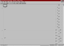
Here is the top part of the logic.

That is true if multi-detectors are going. If there is 40% anywhere, we want it to shut the valves. If a 20% comes up later on another detector, the valves are already shut. The valves are shut by a Shunt trip break and have to manually reset.

Thanks Steve

ladder2.jpg
 
Based on the rung numbers from your posts, I can't tell the order of the SET and RESET instructions. The point I'm trying to make, and which Tom was alluding to, is that the order of the SET and RESET is important.

Let me try to explain that with a simple example. Here's a simple SET/RESET pair, controlled by two inputs.

Start Output
--| |------------------(Set)-

Stop Output
--| |------------------(Rst)-


Here's the truth table:

Start Stop Output
0 0 Maintains previous state
1 0 1
0 1 0
1 1 0


Here's the same thing, but with the order reversed.

Stop Output
--| |------------------(Rst)-

Start Output
--| |------------------(Set)-


Here's the truth table:

Start Stop Output
0 0 Maintains previous state
1 0 1
0 1 0
1 1 1


The difference between the two is the behavior when both Start and Stop are simultaneously true. The state of Output is determined by the last thing it was commanded to do.

In the first example, when both inputs are true, the last command to Output was the Reset command, so Output takes the OFF state.

In the second example, when both inputs are true, the last command to Output is the Set command, so Output takes the On state.

You need to search through your entire logic for all occurrences of SET and RESET instructions for the Y addresses that are giving you trouble, and figure out whether something like my example could be going on.
 
WHOA

Goody said:
After an excellent friday evening imbibiing alcohol and finishing with a curry that was just superb, I could give you an 100% reading for you methane detector.

HMMMM isnt methane a gas? Where would the probe/detector be inserted?
 
Duncan, I wasn't very clear in my response.

All of the logic I showed was intended to be in the PLC. The only thing WonderWare would do is transmitt the reset bit to the PLC to acknowledge and clear the alarm. If you preferred that could be handled by a hardwired reset switch as well. My inent with the PLC logic shown was threefold. First, I wanted to eliminate the SET and RESET commands, which are problematic and hard to de-bug. Second, it is useful to have the system identify which point initiated the alarm, and so monitoring each point individually is beneficial. Third, it is usually helpful to have the system maintain the alarm state until an operator has had an opportunity to observe the status and clear the alarm.

As for the scaling, your initial post indicated you were alarming at 25% and 50% so I worked back from there. You are correct that the 20 mA signal produces 4095 in the associated PLC register. However, the gas detection hardware may be configured to provide 20 mA at 100% LEL, or at 200% LEL, etc. You need to look at your sensor configuration to verify what 20 mA equates to in % LEL. If 20 mA = 100% LEL then your math is entirely correct.
 

Similar Topics

I have a machine which is undergoing upgradation. As part of the process two SEW drives are being replaced., existing Gen B with new Gen C. The...
Replies
3
Views
167
Good morning crew! Ok my logic works but I am missing something. When the start button is pushed it should like the red light for 4sec then shut...
Replies
13
Views
406
Working on project will update after it is completed.
Replies
2
Views
350
Can someone help me piece this problem together. I have a lot of it down I think but cannot seem to get it right. Probably an easy one for most on...
Replies
1
Views
299
Hi everyone, I'm working on a project that involves using a Keyence LR-X100 sensor in Studio 5000 V35 ladder logic to determine the object's...
Replies
4
Views
669
Back
Top Bottom