PLC panel standards

Regarding the placement of VFDs.
VFDs generate heat and are also heat sensitive themselves. They may be rated to be able to sustain a high temperature, but that doesnt mean that you can operate them 100% at the highest rated temperature. Any VFD will be derated if it isnt operated at the 'nominal' temperature, typically 40°C.
Because of that, it makes sense to place VFDs at the bottom. If there are temperature sensitive components in the same enclosure it may be necessary with additional circulation or even cooling. If possible, place VFDs and PLCs in separate panel compartments.
Another thing is that it is the most convenient to terminate the motor cable directly at the VFD. Usually the cable screen can be terminated on the VFD chassis. That also speaks for placing the VFD at the bottom.

I've seen both and can understand both. We use many VFDs and always place at the bottom for the same reasons you mention. The cabling usually comes out of the bottom of our panels and that is closest to the VFD.

I have had some applications where all the cabling comes out the top of the enclosure, however, and place the VFDs on top in that case.
 
Back in the day we used the extra rubber grommets from the Allen Bradley push buttons over the Panduit fingers to hold wires in, especially during the wiring process.
 
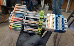
What do you think about using modules like this instead terminals on the very bottom of the panel?

This saves space and time necessary to wire something twice(from cable to terminals and from terminals to PLC), its easy to replace and modify. + and - distribution modules can be added as busbar on the side.

Would be a no-vote from me personally.

I would still wire to terminals, if you are using the Beckhoff servo slice modules then just bring the servo cable to that but it shouldn't be on the bottom row.

I prefer the point IO design where the wiring is on a swing arm so a damaged back module can be replaced without moving wires individually.
 
What do you think about using modules like this instead terminals on the very bottom of the panel?

This saves space and time necessary to wire something twice(from cable to terminals and from terminals to PLC), its easy to replace and modify. + and - distribution modules can be added as busbar on the side.

I've used similar things in the past, such as the Weidmuller slice I/O or the Murrelektronic Cube 20 with the potential blocks below them.

IMO, where the wires are coming into the panel dictates where the terminals should be. It may seem like 'wiring twice' but what it really should do is make the field wiring / installation easier.

When you have the panel in the shop, on the bench (or rack, or wherever) is the easiest time to do good, clean wiring. You don't want to be pulling wires in from the field through the entire wire duct to land on your PLC's terminals, IMO.

If you do, at a minimum you want the terminal blocks to be removable so that you can replace a module without affecting the wiring.


Does it matter for instalator whether they put wires into I/O island or terminals, given it's used in place of terminals and with proper labels?

This way the control unit can stay on the top, or wherever you want it in the panel, and I/O block, connected via fieldbus, is used as terminals.


Apart from that. I think it is also good practice to have all components under the same input voltage. Mixing 24VAC with 24VDC, 12VDC with 48VDC etc., sooner or later, is going to cause problems.
 
Last edited:
This is always appreciated by the installers. Seen way too many panels where there's one fused +24V terminal for the positive feed of the field I/O. Cool... expect me to land 16 wires into that do ya?

I tend to do the same for analogs for things such as level or pressure sensors which may be 2 or 3 wire. Much easier to change something in the middle of the night if you've got +24V, 0V and the analog input + and - right there. 2 wire to 3 wire, no problem.

X3

These sensor blocks work great as do the distribution blocks.

20210205_152735.jpg
 

Similar Topics

Hi, These is an already working plant with HIMA PLC that has a Siemens Comfort Panel HMI connected via Ethernet. HIMA is type 51QHS. I want to...
Replies
0
Views
279
Our a customer has got S5-95U Plc and OP17 Hmi.OP17 is defect.They want to use a new generation Siemens Simatic basic panel (KTP400,700,1200...
Replies
4
Views
1,969
Hii everyone, I am having panel view plus 6 HMI I need to add date and time in Both plc and HMI. I know it's basic thing, Please help me to...
Replies
5
Views
1,722
Hi, I have tried uploading the program from an old Quick Panel 2 using Proficy ME 9.0 and Quick Designer 3.7. I can get the program to upload...
Replies
1
Views
1,447
One of my customer asking an explosion proof HMI + PLC panel for LPG storage tank hazardous zone. The HMI to be for both controlling (by hand...
Replies
5
Views
3,227
Back
Top Bottom