how do I 'queue' machines using PLC & relays

I said...
Instead of using Chk_1, Chk_2, etc in your AND_BOOL's, use CHECK_MTR in all of them.

You said...
If I do that, multiple units that request service at the same time, can start simultaneously (ie. a power outage and all t-stats go high. Power comes up with ALL units requesting svc at the same time). That defeats my purpose. I want to achieve exactly the opposite. I want to NOT allow multiple units to start at the same time.

Also, the SELECTOR uses the output of the counter to scroll thru the motor list. It tries each motor in sequence due to the counter output. Show me a different way to do it and I'll definitely try it.


After any kind of start-up, and all through the day, CHECK_MTR looks for the first motor in the code sequence that is not on but wants to be on.

If it finds one, then CHECK_MTR is disabled and the Timer runs. As long as the timer is running CHECK_MTR is OFF so... no other motors can be started during the timer period.

The program will ALWAYS be scanning the code - it does NOT stop scanning.

When the timer times out, CHECK_MTR is turned on again and the program looks again for the first motor in the code sequence that is not on but wants to be on.

While Check_Mtr, if Mtr3 wants to be started...
Start_Mtr3
Disable Check_Mtr and begin 30-Sec Delay
@Timeout - Enable Check_Mtr

While Check_Mtr, if Mtr8 wants to be started...
Start_Mtr8
Disable Check_Mtr and begin 30-Sec Delay
@Timeout - Enable Check_Mtr

While Check_Mtr, if Mtr2 wants to be started...
Start_Mtr2
Disable Check_Mtr and begin 30-Sec Delay
@Timeout - Enable Check_Mtr

etc...

The fact that CHECK_MTR is turned OFF is what prevents any other motors from starting during the timer period. The program continues to scan ALL start_motor requests but none can be serviced as long as CHECK_MTR is OFF.

As far as the number of logic blocks... I didn't mean the number of types... I meant the actual number of blocks that you can load into the program.

You might have 5 logic block types. The program might allow a total of 32 blocks (in any "type" combination).
 
Last edited:
Terry, I printed Allen's code section (the re-coding of your original code). I read it in a calmer environment. I follow the logic just fine. It still looks to me like multiple machines will be allowed to come on if , during a single scan, the PLC finds more than one machine to service.

I tried your method on a small system about 3 years ago. The first time power was restored after a power outage, all the units needed service. Guess what? All the units came on immediately. The PLC serviced ALL of them at the same time.

I've been using the term 'scan' without regard for the fact that PLC programmers understand scan to be the process of running thru it's I/Os. I've been referring to the process of running thru my 'sequence'. Sorry 'bout that!

I'll try your method this a.m. Hopefully, I'm wrong and you're right. It'll save a LOT of headaches.

Thanks for your patience.
 
Hickman:

No, two motors cannot come on simultaneously, even if, in a single scan, two motors are requested to start.

The key is that, AT THE SAME INSTANT, in the middle of the scan, that one motor is allowed to start, the CHK_MTR (Terry's phrasing, or ALLOW_ANY_START, my phrasing) bit is reset. The next time (even in the same scan) that the PLC goes to evaluate that bit, the bit will be off, and the second motor will not be allowed to start, until the bit is set again via the timer.

Now I acknowledge that I'm very rusty on Concept FBDs (the last project was 5 years, 3 companies and 4 PCs ago - I don't even have the software installed to verify things), but for most (all?) PLCs, the regiser memory is re-read every time an address (tag) is encountered. So if, in a single scan, I read from an address and it's set, then reset it, for the remainder of the scan that bit will be reset (unless I set it again further down the pike).

With traditional ladder, scan order is usually clear: rung-by-rung, top-to-bottom, left-to-right. (Modicon 984 does it left-to-right (rung independant) then top to bottom - this drives many experienced programmers nuts, especially since coils don't have to be at the right-most point in space)

I don't remember how scan order is determined in Concept. It MIGHT be possible that, with poor design, ALL your AND_BOOL's could be scanned before any of your SRs, thereby ruining the strategy that Terry & I have laid out. That is, the logic for the evaluation of CHK_MTR would have been done by all 12 motors before the actual start of the motor (and resetting of the CHK_MTR bit).

If that's the case, then you would be right. I don't know, it's been too long. But if I remember correctly, that little parenthesis above the FB contains the scan order. If you order things correctly, then the logic will work.
 
It occurred to me that your "processor" might actually be a "programmable gate array".

If so... then there ain't no "scan" at all... it's all "real-time".

If that is the case...
Then maybe the way to go is something like this... (stick your tongue out, cross your eyes, gyrate your arms and legs crazily and "walk this way".)

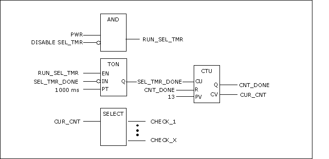
Keep the selector.

Set the increment timer for the selector (SEL_TMR) to 1-second.

While no "Calls" are ON, the selector will scroll through, reset and scroll through again every 13-seconds.

3f43601923e57fdf.gif


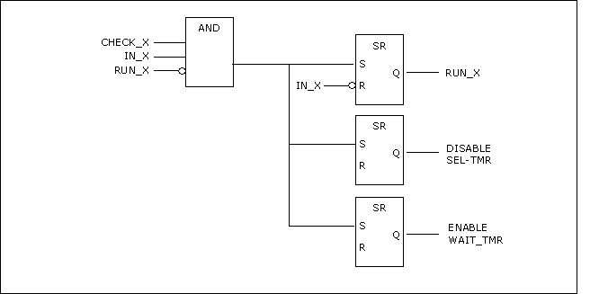
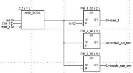
When CHECK_X and IN_X and NOT RUN_X then...
SET RUN_X until IN_X goes OFF
SET DISABLE_SEL_TMR
SET ENABLE_WAIT_TMR

The Inputs to these SR's go off as soon as RUN_X goes ON.

3f43606616c6e0a1.gif


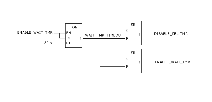
With DISABLE_SEL_TMR turned ON, the SEL_TMR stops running.
With ENABLE_WAIT_TMR turned ON, the 30 second timer runs.
When the WAIT_TMR times out...
RESET DISABLE_SEL_TMR
RESET ENABLE_WAIT_TMR


3f43609768da7ac4.gif


The selector should pick-up were it stopped and continue through the list until the next motor call is found.

Does that look a little closer?
 
How would I know if it's a programmable gate array as opposed to a processor?

Either way, it's interesting that you present this approach. I looked it over again last night before I went to bed and determined that I should take a similar approach to what you've preposed here.

I'm going to try to give it a whirl today. I'm a computer consultant and have several calls today. Maybe I'll get around to it tonight. I'll post to let everyone know how it goes.

Thanks for all the help. Especially Terry and Allen for hanging in there with me. (y)
 
Let's see if this helps...
PC I'm using to write this doesn't have any PLC software
but if you are familiar with AB PLCs, following should
give you an idea. Just use listed Address / Symbol and
then add comments for individual bits (eg.
B3:4/2 "Signal from Stat-PB for Motor2 - blah blah ...")

T4:0 Startup delay timer
N7:0 Search scan
B3:0 Start in progress
B3:1 Start Pulse
B3:2 Start Select
B3:3 Motor Started
B3:4 Start Command
B3:5 Stop Command
B3:6 Motor Running
B3:7 Was Running


; Scan for next motor to be started. Stop scanning during motor startup...
XIO T4:0/TT BST ADD N7:0 1 N7:0 NXB XIC B3:2/15 CLR N7:0 BND
SOR DCD N7:0 B3:2 EOR

; See if selected motor is running
SOR AND B3:2 B3:6 B3:3 EOR

; If selected motor wasn't running before, it is started just now
SOR XOR B3:3 B3:7 B3:0 EOR
SOR BST NEQ B3:0 0 NXB XIC T4:0/TT BND TON T4:0 1.0 30 0 EOR
SOR SUB B3:0 B3:6 B3:1 EOR

; Remember if motor was already running
SOR MOV B3:6 B3:7 EOR

; Motor Logic for up to 16 motors
SOR BST XIC B3:4/0 XIC B3:1/0 NXB XIC B3:6/0 BND XIO B3:5/0 OTE B3:6/0 EOR
SOR BST XIC B3:4/1 XIC B3:1/1 NXB XIC B3:6/1 BND XIO B3:5/1 OTE B3:6/1 EOR
SOR BST XIC B3:4/2 XIC B3:1/2 NXB XIC B3:6/2 BND XIO B3:5/2 OTE B3:6/2 EOR
SOR BST XIC B3:4/3 XIC B3:1/3 NXB XIC B3:6/3 BND XIO B3:5/3 OTE B3:6/3 EOR
SOR BST XIC B3:4/4 XIC B3:1/4 NXB XIC B3:6/4 BND XIO B3:5/4 OTE B3:6/4 EOR
SOR BST XIC B3:4/5 XIC B3:1/5 NXB XIC B3:6/5 BND XIO B3:5/5 OTE B3:6/5 EOR
SOR BST XIC B3:4/6 XIC B3:1/6 NXB XIC B3:6/6 BND XIO B3:5/6 OTE B3:6/6 EOR
SOR BST XIC B3:4/7 XIC B3:1/7 NXB XIC B3:6/7 BND XIO B3:5/7 OTE B3:6/7 EOR
SOR BST XIC B3:4/8 XIC B3:1/8 NXB XIC B3:6/8 BND XIO B3:5/8 OTE B3:6/8 EOR
SOR BST XIC B3:4/9 XIC B3:1/9 NXB XIC B3:6/9 BND XIO B3:5/9 OTE B3:6/9 EOR
SOR BST XIC B3:4/10 XIC B3:1/10 NXB XIC B3:6/10 BND XIO B3:5/10 OTE B3:6/10 EOR
SOR BST XIC B3:4/11 XIC B3:1/11 NXB XIC B3:6/11 BND XIO B3:5/11 OTE B3:6/11 EOR
SOR BST XIC B3:4/12 XIC B3:1/12 NXB XIC B3:6/12 BND XIO B3:5/12 OTE B3:6/12 EOR

 
What's a 'concept'?

hickman said:

Concept has approx 2 dozen logic blocks, including AND, NOT, OR, XOR, ROL, ROR, SHL & SHR.

I've never heard of this 'Concept' thing. Do they have a website?

Does the controller have a FIFO structure - or could one be built up out of other logic blocks?
 
Panic Mode,

Your code is based on the idea that there is a "scan", as in PLC-scan.

From what I've seen from hickman, this appears to be a programmable "real-time" gate array. It operates in exactly the same manner as a hard-wired system - so, no scan.

For a lot of us it requires getting out of "scan mode" and back into "real mode".

I'm gonna wait to see what hickman has to say about his latest attempt.


Doug-P,

I don't know anything about "Concept" but whether or not it can actually do FIFO depends on whether or not it has access to V-Mem. If it doesn't, then the answer is NO. If it does, then it depends on the functions available. Having "2 dozen logic blocks" available does make it sound possible. However, just bearly so, if at all.

Again, I'm gonna wait on hickman's response.
 
Gave it a try...

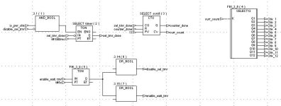
Ok, PLC fans. I made an attempt at the code. I may be doing something wrong, but NONE of the SRs are working. I'm wondering if a Reset is required. I'm trying OR_BOOLs in there place, but the variables are never getting set.

I've attached a snapshot of the main procedure (Section1) and a portion of Section2 (duplicated for each unit).

Maybe something's getting lost from your IDE to mine (Concept).

section1.jpg
 
response to Panic Mode

Panic Mode: I have NO idea what that is! Did you're computer dump it's registers to screen or what?! :D

I'm into visual programming. I tried to forget Assembler just as soon as I finished the final exam!
 
Hickman...

You said...
I may be doing something wrong, but NONE of the SRs are working. I'm wondering if a Reset is required. I'm trying OR_BOOLs in there place, but the variables are never getting set.

You are using Or-Bool's in whose place?

From what I see in your first drawing the "enable_wait_timer" goes to a hang_state... always ON.

If IN-1 is ON, and MTR-1 is NOT ON, then at Check-1, "enable_wait_tmr" goes TRUE. That starts TMR(5). As soon as TMR(5) times out, it again asserts "enable_wait_tmr". Then TMR(5) and OR_BOOL(7) fall into an endless loop - a hang.

I suspect that if you start the process with IN-1 ON, then Motor-1 will start and then the system will hang.

I think you might want to revisit Post #19.
 

Similar Topics

The idea here is to provide for a brief rapid influx of message codes while preventing sequentially repeating the same message. i.e. if two...
Replies
23
Views
668
I'm fairly green at PLC programming compared to everyone here. I have a firm understanding of most commonly used instructions. Everything I've...
Replies
19
Views
8,131
Hello everybody. For a project, I need to make a queue that stores REAL's. There needs to be the possibility to select a place and than move the...
Replies
9
Views
2,473
So, I'm very new to PLC and HMI's and I was asked to investigate something that occurred with my client's system: They set up a queue list of...
Replies
2
Views
1,545
Well can anybody give me a head start on some logic, I cant just seam to get a start. What I need is 4 lanes to queue and and which ever lanes is...
Replies
13
Views
2,982
Back
Top Bottom