Panel view 600 to control logic L63

Holmsy

Member
Join Date
Jul 2003
Posts
5
Trying to connect an old panel view 600 to a control logic processor over device net

I have devicenet connected but can't seem to address the tags properly

I know I need to use the plc/slc but can't find an example

Any help would be great
 
I have the scanlist. Done and the dnb setup but can't seem to create tags that the panelview will except
 
Please refer to the manual I linked previously.

You need to configure FactoryTalk Linx communication setup and create your Input & Output Aliases in the I/O Configuration. These Alias tags will be what your PV will address.
In the Tag Browser>Online> you will see the Alias tags from InputTable / OutputTable that was created.
 
Welcome to the PLCTalk forum community !

What is the exact part number of the PanelView terminal ? Is it a "PanelView Standard" with the black bezel, or a "PanelView Plus" with a gray bezel ?

Are you using the ordinary DeviceNet interface, or are you using a 1761-NET-DNI serial bridge ?

The PV+ is very difficult to use on DeviceNet, but the older PV Standard aren't too bad.
 
Ken

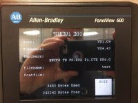
It is an old PV 600 attached is a picture

Also here is the Control logic file

DNB is in slot 4

PV 600.jpg
 
OK, that verifies that the terminal is a PanelView Standard. I believe that the "P1.CTK" on the information screen means that it's equipped with a DeviceNet daughtercard, but a photo or the exact part number would be conclusive.

The *.ACD file is for a 1756-L63 with Version 13 firmware, so you're probably running RSLogix 5000 in Windows XP or Windows 7, and have RSNetworx software for that generation.

Your test program also doesn't appear to have used the DeviceNet Tag Mapping Tool, which created logic that mapped out data from each DeviceNet scanlist entry to ControlLogix tags, so you're starting from scratch there.

You will need the 1756-DNB Scanlist to know where in the Local:4:I.Data[x] and Local:4:O.Data[x] array tags the PanelView data goes.

In the PanelBuilder32 software itself, the Input and Output images are really pretty straightforward syntax.

They are literally I:<word/<bit> and O:<word>/<bit> for each Word of the I/O Assembly. The I/O assembly can be up to 64 16-bit Words in each direction.

To my knowledge the PanelView's syntax was always 16-bit on the DeviceNet side, since it was built to work with the 16-bit SLC-500 and PLC-5 DeviceNet scanners. When you use it with a 32-bit DeviceNet scanner with a ControlLogix, you just have to account for two Words in every I/O image DWord.

RA Knowledgebase Article 32024 discusses that a little bit, but it really is just as simple as "copy 32-bit DINT data into a 16-bit INT tag array if it helps you understand and use it better".
 

Similar Topics

Hi Everyone, I am new to the site and to plc programing. Always been the guy trouble shooting around them. I have a Panelview 600 2711-b6c8...
Replies
6
Views
1,314
Hello everyone I have a PanelView Plus 600 that is acting up. To be able to go into our manual operations of the machine it runs, a small fluid...
Replies
18
Views
4,964
Dear expert /Group members Good day to your Does anyone have this problem? Problem explanation as below :- Thanks in advance
Replies
1
Views
1,044
Hello everyone, im new in Allen Bradley World, i alredy know how to use factory talk view and with manager i have alredy upload all runtime...
Replies
1
Views
1,681
please i need help in the allen bradley panel view 600 in this i need how to attached the function keys for respective function f1,f2,f3 etc all...
Replies
1
Views
1,505
Back
Top Bottom