Pneumatic relay for smart positioner/control valve

Theboss

Member
Join Date
Jun 2010
Location
Durban
Posts
159
Hi Gents,

Please could someone assist me in understanding this piece of equipment as to how it works. Any feedback would be greatly appreciated.

Correct if I'm incorrect. As your supply air to the relay is throttle which is 20-100kpa from an i/p converter , it switches a greater pressure through its output, to drive an actuator. Supply air could be 4-6bar.
 
A control valve is the device in the pipe that opens or closes to regulate the flow of air/liquid.

An actuator is the mechanical device that controls how open or closed the valve. A handwheel is a manual actuator.
There are pneumatic and electrical actuators that open or close valves. Some are rotary. Some are linear.

The control signal to an actuator for a modulating valve can be control pneumatical (3-15psi or 20-100kPa) or electric (4-20mA, ProfibusPA, Foundation Fieldbus)

An I/P converts an electrical 4-20mA control signal to a pneumatic 3-15psi/20-100kPa signal.

The problem is that the actuator can not position the valve at the same point as the control signal desires because of 'stiction' friction/sticking.

The solution to getting a valve to alway be at the position demanded by the control signal is a positioner.

A positioner is a controller that senses the valve's mechanical position (0-100% from open to closed) with mechanical linkage.
The valve's position is the controller's input. The control signal is the setpoint. Any difference between input and setpoint is an error. The positioner's controller takes action to force the position of the valve by the actuator so that there is zero error.

Historically, there were
- pneumatic positioners which took a pneumatic control signal and used an air supply of a higher range to apply the force in a pneumatic actuator necessary to correct the valve position.
- electronic positioner which took an electrical control signal (4-20mA) but used pneumatics and a higher range air supply to work with a pneumatic actuator to force/correct the valve position.

An I/P cannot provide a higher air supply pressure than its rating. A positioner can use higher air pressure on its output which the actuator uses to apply force to get the valve to its position.

Mechanical cams were used to convert from the output characterization from linear action to equal percentage.
Setting up a pneumatic positioner could take 2 hours.

Smart positioners have evolved over time. Smart positioners use electronics (and an air supply for the output) to do what pneumatic positioners do. actions like convert output characterization from linear to equal percentage or diagnostics. Smarts can use fieldbus control signals and provide feedback over a fieldbus.

Smart positioners require DC power and use an electronic input control signal.
 
Last edited:
Thanks Dan. I expressed myself incorrectly. What I meant to say was. Does the pneumatic relay throttle the supply pressure(eg. 6bar) to your actuator with respect to your 20-100kp or 3-15psi input air supply to the relay(which comes from the i/p). Am I correct in saying this or have I got it wrong?
 
I'm thinking off a pneumatic relay almost the same as how an electric relay works but a pneumatic relay has a variable input(3-15psi) which then throttles your 6bar supply pressure to the actuator to drive valve.
 
I can't answer your question about a "pneumatic relay" because that can be different things depending on definitions. Electric relays are on-off devices. But 3-15psi is a linear, continuous output proportional to some input.

If it has a variable 3-15psi output, it is probably an I/P where 3-15psi output is linear with the 4-20mA input.

An I/P only needs sufficient supply air pressure to achieve the its rated 15psi or 200kPa output.

An I/P can not make an adjustment if a valve sticks at 30% when the control signal is at 33% because an I/P has no feedback from the valve and does not know that there is an error.

A positioner will supply more than 15psi or 200kPa (it wants a higher supply pressure) to the actuator (within limits) in order to correct the error in order to get the valve to 33% position.
 
Il check up on that. All I know that it's on a fieldvue dvc 2000 smart positioner.

Going back to an i/p. I understand how it works. I'm trying to figure out the i/p output which is generally 3-15psi. What happens next in terms off the principle operation. Because sometimes I see two types.
1. The supply press to the i/p is 140kpa with a separate 6bar supply pressure (mite or Kent positioners) then two outlet pressure lines to actuator.
2. Supply pressure to i/p is 2-6bar and one outlet pressure line to actuator.

This is my concern because I don't understand these two types of positioners. Please help.
 
DCV2000 is a single acting positioner. So you just connect supply pressure to one port (that must på 0.5 bar higher than the valve actuator needs) and then it will send pressure on the other port that needs to be connected to your valve actuator.

The actuator needs to be spring closed or spring opened.

There's an option with a valve position transmitter as well if you need feedback to your control system.

Here's all information you need:
http://www.emerson.com/documents/automation/135208.pdf
 
Last edited:
and then it will send pressure on the other port that needs to be connected to your valve actuator.
Of course proportional to the applied current signal (4-20mA), according to your calibration. Calibration procedures found in the previous link.
 
I want to know what's the difference between the two types I mentioned and working principle of the the two types.
 
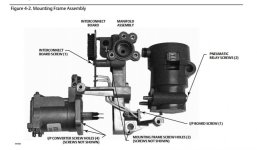
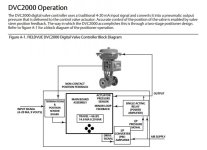
You'll find the working principle in the manual. It uses an I/P-converter together with a pneumatic relay. Both takes air from the same feed as you only have one feed in.

The I/P-converter is for low flow/volume. The Pneumatic relay is probably there to get a larger airflow. Otherwise you'd need a much bigger I/P or get a very slow valve action, depending on the actuator size (volume).

You want to replace a DCV2000 with just an I/P-converter?
 
Last edited:
Oh k will have a look.
And what about the other positioner where there is a 140kpa supply to the i/p and a separate 6bar pressure to the positioner
 
an I/P valve is proportinal and has nothing to do with a relay.
The coil (taking 4/20 mA) is pulling on a lever and on the other side the pressure of the output.
If the pressure is low the small pin will open to get more pressurefrom the airsupply to get the correct pressure.
the output is 0.2 to 1 BAR.
This signal is connected to the position controller.
The pressure is on one side and a spring connected to the stem is on the other side.
again same so the controller will put the stem on the required position.
sometimes there is also a amplifier for this.
It is all moving analog and not with relais.
 

Similar Topics

I have an actuator operating a clamp that requires PLd/SIL3, I’ve seen some SMC double valves with feedback, but they are described as dump...
Replies
9
Views
2,346
Dear experts, i have pretty basic/ dump question, can someone help me to figure out how to read/ what is this? i assume it is solenoid vavle...
Replies
4
Views
1,057
If anyone has any information on how this sensor operates or has one they would be willing to sell, need it ASAP. Old machine is down because of...
Replies
0
Views
1,131
I am looking for different solution on controlling a pneumatic Cylinder move at preset positions. One of the solutions is to use 5 magnetic...
Replies
22
Views
5,969
Replies
6
Views
3,815
Back
Top Bottom