Valve Control with VSD

boneless

Lifetime Supporting Member + Moderator
Join Date
Feb 2008
Location
OKC
Posts
1,628
Hi all,


I have a customer that has managed to order an AUMA valve without positioner. From experience, we do not want to implement a contactor based direction changer (to open-close valve).
Has anyone ever done valve control with a VSD?


The valve is used for controlling temperature, and is expected to move a lot (between 25-100%). It will usually only close when the system is stopped.
 
I've used a drives built in AO to drive a valve before. Recomend putting it through an isolating barrier first to protect the drive IO.

Even used in in conjunction with a PID loop built into the drive.

What model of VSD are you planning on using?
 
Thank you Rob,


I am just brain-storming right now, we kinda put the ball in the customers corner. We have a couple of ABB ACS580 for pumps, so it would likely be a similar drive, using profibus coms.
 
As Rob said, some drives have a PID operation mode built in. Not sure how well they work as I've never had to use one but I can't see it being a bad option if the manufacturer puts it in the drives. I've specifically seen PID modes on Eaton PowerXL drives, not sure about the ABB drives.
 
I'm confused. If you're asking about a VFD, presumably the actuator is an electric actuator.

Typically electric actuated valves use either a conventional control signal, like 4-20mA or dual relay, where one relay drives the valve open, the other relay drives the valve closed, which is what I think the reference to 'contactor' was about.

TPSC-drive-open-drive-closed-1.jpg


TPSC-drive-open-drive-closed-1.jpg


I have seen very high torque actuators use an 'internal' VFD, as part of an integrated design, to drive the actuator motor, but the integrated design had the VFD taking a conventional 4-20mA control signal and the motor was designed for that service.

How would you take a typical electric actuator with a drive-open coil and a separate drive-close coil and run it from a VFD?
 
You guys are missing the point. The Valve has no positioner, so he wants to use a VFD to go fwd and rev to open and close the valve. My first thought is don't do it. How will you know if the valve is fully open or fully closed? Do you have limit switches?
 
On 2nd thought, if DanW is correct, you just need two outputs, one to open and one to close. I have seen dampers at Waste treatment plants that had motor controls that worked that way. Then some simple logic to open and close the damper, using pulsed outputs.
 
You guys are missing the point. The Valve has no positioner, so he wants to use a VFD to go fwd and rev to open and close the valve. My first thought is don't do it. How will you know if the valve is fully open or fully closed? Do you have limit switches?

Auma valves have their own control system inside. With limits etc etc.

Used a lot on waste water sites.

Usually have their own 3phase supply and a position signal. With a 4 - 20mA signal, send 12mA to the valve it'll move itself to 50% open.
 
Hi guys,


Yes I know the AUMA supplied positioners, they are great. My customer "forgot" to order them with the valves. So all we have is a valve, with a 3 phase motor, position feed back, and limit switches.


They do not seem to understand the issue, we have told them to return the units to AUMA and let them add whatever they need to make it suitable for our system.


So I am just brain storming possible solutions here, my idea for using a VSD is to be able to slowly jog the valve motor, in either direction, using the pot meter as feedback.

We have done this with contactor based motor reversing, but it has shown to be pretty hard on the system.


So, again, the thought just crossed my mind and I was wondering if any of you has done it this way before.


Thanks again!!!!
 
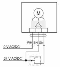
You can see the separate coils for driving clockwise (CW) or Counter Clockwise (CCW) in the top graphic. The coils are represented as straight lines on a 45° angle in the lower graphic. Only one relay is every ON at any moment.


Actuator-wiring-3000-hi.jpg


Controller-with-drive-open-drive-closed-relays.jpgttp:


The actuator's factory control circuit should give you the means of controlling it.


There are signal conditioner modules that take a 4-20mA and convert to drive-open/drive-closed relay logic, if there's a voltage/current signal or slidewire that provides position feedback.
 
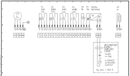
Hello, first things first. What is the actual wiring diagram of the AUMA drive you're talking about? Is it something like this?
http://www1.auma.com/uploads/media/.../antriebe_mit_steuerung/aumatic/sp_a1n_en.pdf

I have seen a lot of AUMA drives controlled by discreete 24VDC with step controllers and very good performances especially in control temparature applications. For control applications SAR drive is used (SA for ON/OFF). For control drives thyristors are used and contactors for On/Off.
If you have position feedback and limit switches, you basically have everything that you need.
So first, please tell us or better upload actual wiring diagram of AUMA drive. On official AUMA web page you can download actual wiring diagram of the drive, based on order number, which is great.
https://www.auma.com/en/service-support/wiring-diagrams/
 
Hi Pandiani,


It is as I describe above, a bare-bone AUMA valve and actuator, see attachment.


And your reply brings up another issue that we have, they purchased an SA actuator. Not SAR.

auma.PNG
 
Hi Pandiani,


It is as I describe above, a bare-bone AUMA valve and actuator, see attachment.


And your reply brings up another issue that we have, they purchased an SA actuator. Not SAR.

https://www.auma.com/products/multi-turn-actuators/actuators-sa-and-sar/
SA is not for control application. Drive is not selected properly. SAR actuators have motors and insulation designed for intermittent operations. SAR combines with control boards with thyristors for control applications. The designer should use equipment for intended purpose. Everything else is improvisation and not very long life cycle.
 
Last edited:

Similar Topics

I have been requested to test this proportioning valve for PLC control of flow/pressure. Dwyer Series SVP Proportioning Solenoid Valve The flow...
Replies
10
Views
408
So I'm pretty green when it comes to troubleshooting in the field so bear with me. We have a Danfoss valve that opens/closes from an analog output...
Replies
23
Views
944
Hi there, We have a system at a water treatment plant where large raw water tanks feed into the plant that's all on the same level. At high tank...
Replies
18
Views
3,743
Working on a site where they are using a DeltaV DCS system. They are using Topworx DVC6200 controllers on their modulating valves. These control...
Replies
1
Views
1,035
Does anyone have any experience in this? I have a lead lag pump setup for water that is maintained by pressure using VFDS, the idea is to have...
Replies
6
Views
1,826
Back
Top Bottom