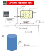
Need help with PID control please!

sparkytex

Lifetime Supporting Member
Join Date
Jun 2013
Location
Port Hardy B.C.
Posts
354
I have a few questions about a PID control I have to make changes too. Here's the low down; The PID control is used to control temperature of our pulp being transferred to our D1 tower. The process variable is a temperature transmitter scaled from 0-100. The control variable is a analog valve (0-100%) that allows steam to enter the pipe that carries the pulp to the D1 Tower. Obviously the more the valve is open the more steam gets in and spikes the Temperature of the pulp that is carried to the D1 Tower. Currently they run the PID on manual with a output of 12% open on the valve which keeps the temp around 40 degrees Celsius. They do not run it in auto due to the fact the temperature transmitter is inaccurate and it just doesn't ever meet the setpoint. They have a temperature transmitter that is closer to the D1 tower and that is more accurate and they want me to initiate that TT (temp. transmitter) as the new Process variable for that PID control. An issue here is that the TT they want to change to is quite a ways further away from the old one and there's quite the delay in temperature change as well as some different scaling between the two TT's. I got the operator to open the steam valve to 40 % and timed how long it took to make a change in temperature. It took 5 minutes and 45 seconds to change. I'll list off the current parameters of the PID;

(I'm using RSLogix5)

KP - 0.5
KI - 0.0001
KD - 0.1
Output Bias % - 3.28074 ( I don't understand what this is for)
MINS - 40
MAXS - 100
DB - 0
MAXO - 100
MINO - 0
UPD - 2
PVH - 90
PVL - 70
MAXI - 32767
MINI - 0

First of all I don't understand what the output Bias % is for. Also the old TT that is used is scaled to 0-100 just like the new one but in the I/O config its scale low is 0 and its scale high is 32767 (raw data). The new TT is scaled in the I/O config as scale low 0 and scale High 100. Why would the MINS in the PID be 40 if the current TT is supposed to be from 0-100? I changed the process variables on the PID from N40:7 (old) to N46:7 (new) but issues arose since the scaling doesn't match up. Since the new TT is scaled in the I/O config, do I need to change the MAXI and MAXS to 100 and the MINI and MINS to 0 in the PID? Right now the PID isn't even showing a process error when I have it in auto even though the Setpoint it 36 and the PV is 40 degrees which should be a Process error of +4. I need some help with these Scaling issues for the New TT and the PID as well as what the Output Bias % is and how to estimate a derivative time.

I'm quite new to PID control and im beating my head against the wall:mad:

Thanks, Tex
 
Where's your process engineer?

I would go back to the drawing board. Sound like they are just taking a stab in the dark and hope it works. I see some red flags right off the bat. In my experience, trying to control temperature by modulating the steam valve never works well. Steam quality varies. It's much more typical to use a cascade loop for such control where the inner loop control just the amount of heat and outer loop manage the temperature.

The process engineer hasn' had much experience in tuning PID loops just like myself. I've only ever had set up communications between the PID loop with an HMI writing data to it. The PID math has always been set up and tuned already. I've also never set up a cascade loop control. done some reading about it but not quite sure exactly how it works. The outer loops looks and the temperature of the pulp. the error of this loops sets a goal for the inner loop to adjust the steam valve right? does the control variable of the outer loop set that goal for the inner loop?
 
here's a good write up on cascade control I just googled:

https://controls.engin.umich.edu/wiki/index.php/CascadeControl

Determine what is the variable you want to control, that will be your process variable. The rest of the exercise is just to have a system that get your PV to be with your setpoint. Cascade loop may or may solve your problem, it really depend on your process condition, the variability of your steam quality (heat content).

You might want to take up the cascade loop question another day, back to your PID setup. From the instruction help:

Output Bias %

Enter a value (-100 to +100) to represent the percentage of output you want to feed forward or use as a bias to the output. The bias value can compensate for steady-loss of energy from the system.

The ladder program can enter a feedforward value to bump the output in anticipation of a disturbance. This value is often used to control a process with transportation lag.


can you tell us if the PID block is using a PD block or N type block?
 
Last edited:
List 4 u to check.

1.) the instrument location to be install are the right/best location?

2.) what type of temperature sensor to be use?
a. PT100 b.TC

3.) Using Analog Transmitter 4-20mA? 0-10VDC ?0-5VDC?etc.
as interface to PLC?

4.) Calibration/spec on this Analog Transmitter?

5.) Type of PID - feedforward/cascade?

6.) Request from process engineer the unit/value to be use?

7.) SLC500 Pid for feedforward/cascade are available???

CASCADE.jpg
 

Attachments

  • UDC 3500 Cascade Control.pdf
    89.9 KB · Views: 46
The BIAS is used to implement feed forward control. For instance, the temperature may increase 3 degrees per %control output. If you want to control at 100 degrees above ambient then you could set the bias to 33.33%. The 3 degrees per ambient is accurate then you don't even need a PID but unfortunately loads change. The PID should only be necessary to handle non-linearities and changes in the load.
 
as the time is very long use both sensors in a complicated or cascade way, the fist is used for the P action and the other for the I action
 
Well here's another issue. The temperature Transmitter that is being used as I said was scaled in the I/O config as scale low - 0 and scale high - 100. This makes the TT scaled from 0-100. Right now its showing 41 degrees C. When I manually spiked the valve that controls the steam from 17% open to 40% open the temperature climbed up to 52 degrees C after about 5 minutes. I have the PD80:5's setup screen up on RSLogix5 to watch the Process error and I noticed the damn Process Variable isn't updating. It takes the word N46:7 right from the 1771 NIS analog input card. I could confirmed that in the I/O config I could see 52 Degrees C but not on the PID setup screen. Now why would this not be updating the Process Variable (N46:7). it still seems a bit strange why someone scaled the TT in the I/O config in the first place. Why not have 0-32767 or 4000 to 20000 then use that as your MAXI and MINI in the PID setup. Right now the MAXI is 32767 and MINI is 0 which I don't get because the max scaled value in I/O config is 100. Also the MAXS is 100 and the MINS is 40? somethings not adding up. Why is the PV not updating to current conditions, any help would be appreciated as this is making me mental!!

thanks
 
Your PID is in the manual mode in the file you sent. This should not effect the process update though just the output (CV)

From the file you sent it appears the process variable is correct. Can you take a snap shot of when it is not?

You have the loop update set at 2sec. in the PID configuration, you should have a self-resetting timer set at 2 sec. Then use its DN bit on rung 068 instead of the PID's EN bit.

I would set the min/max input to 0-100 and the min/max engineering unit to 0-100. If you do this be careful the wrong data can fault the controller.
 
Last edited:
"the damn Process Variable isn't updating. It takes the word N46:7 right from the 1771 NIS analog input card.
I could confirmed that in the I/O config I could see 52 Degrees C but not on the PID setup screen."

Even though your 2 values are effectively equal, they don't have to be.

The process variable (PV) (displayed on the PID setup status tab) is a sub element of the PID control block, and has a
different address. For example; PD80:5.PV is the Process Variable shown in the PID setup status tab, but the actual integer
address now used as PV for the PID instruction is N46:7. It is possible for the two values to be different, after/because of PID scaling.

i.e.; displayed Process Variable PD80:5.PV (scaled by PID) not equal to Process Variable N46:7

N40:7 is scaled in the PLC program, N46:7 is not.
 
I have the PD80:5's setup screen up on RSLogix5 to watch the Process error and I noticed the damn Process Variable isn't updating. It takes the word N46:7 right from the 1771 NIS analog input card. I could confirmed that in the I/O config I could see 52 Degrees C but not on the PID setup screen. Now why would this not be updating the Process Variable (N46:7).
Remember that the definition of "Manual" mode for the RSLogix PID instruction is that the PID Setpoint is passed directly to the PID Output Control Variable, and the Process Variable is ignored until you switch back to "Auto" mode.
Currently they run the PID on manual with a output of 12% open on the valve which keeps the temp around 40 degrees Celsius.
 
I do know that in manual mode it writes directly to the control variable output. However when I put the PID in auto is does not update the Process variable in the PID setup screen menu as well as the process error. So when I put the PID in auto the process variable does not move at all and the PID keeps trying to compensate for that by bumping up the control variable output. I've been trying to figure this one out for quite some time.

Edit** I can see the value of N46:7 on wonderware just fine, its showing 43 degrees. N46:7 is the address used in the PID's process variable, that's why I don't understand why it wont update or register the correct number. If I use PD80:5.PV as the readout on wonderware its the same issue whether in auto or manual it does not update, its just stays at 40 and doesn't move even though you can see the value of N46:7 changing.

Also I just tried something different. I took the channel address N46:7 and scaled it from 0-32767 in I/O config instead of 0-100. In the PID control I made sure the MAXI was 32767 and the MINI was 0. I then changes the MAXS to 100 and MINS to 0 so this thing is scaled 0 to 100. The raw data of the channel address is 14049 which is 42 Degrees celcius. But on the PID set up menu PD80:5.PV is reading 27 degrees instead of 42. Why in the hell would it be taking off 15 degrees? I made a CPT function of (N46:7-32767)*100 with the destination being F8:240, I then moved it to N25:1. So now N25:1 reads the correct scaled value from 0-100. I tried to use N25:1 as PD80:5's Process Variable and it just wouldn't work.
 
Last edited:

Similar Topics

hello guys I'm having problem in pid in Omron cp1l plc I have program . I'm getting alarm when I execute pid
Replies
1
Views
2,807
I currently have a pressure switch and a back pressure regulator. I am planning to replace the regulator with an E/P electronic-pneumatic...
Replies
9
Views
4,402
I just programmed a PID control system for a VFD to control header pressure for our weak liquor pump to our evaporators. I tested out all the...
Replies
4
Views
1,891
Hello, I'm an intern at this power plant and I'm new to PLC programming. I'm hoping to get some help from the professionals in this forum. I...
Replies
22
Views
5,902
I am working on a CIP project. There is a tank which is about 1500L. We need to keep the water volumn inside the tank to be SP:200L. The control...
Replies
17
Views
10,832
Back
Top Bottom