By George, I think I've got it!!

jaywillnot

Lifetime Supporting Member
Join Date
Apr 2015
Location
Alabama
Posts
69
After months of beating my head against the keyboard o_O trying to figure out why my programs wouldn't work the way I expected them to, I read one post on here (don't remember which post it was) that put everything into clear perspective.

For the life of me, I couldn't figure out the difference between "virtual" XIO contacts and "hardwired" NC contacts. I then realized after reading the post that the proverbial light went off in my noggin. Basically the PLC has no idea how the field devices are wired, and frankly it doesn't care....all the processor knows is 1 or 0, On or Off

It was driving me crazy why a physical E-Stop button with normally closed contacts would be written as a normally open condition....that was until I sat down with a practice PLC, a (NO) push button, a (NC) stop push button, a relay, and a couple of LEDs. While I was wiring them up in different variations to pass and fail, I realized that even though when we write a conditional rung with a normally closed condition the state of that condition and the state of the field device can be two totally separate entities, operating in two different fashions (ie, if the NC input is in-fact virtual and needs no outside signal to energize or if it is receiving signal from a real world switch, PB...etc)

I can't believe it took me this long to figure out the difference between real world relay logic and processor relay logic. But I guess that's one of life's lessons learned as a maintenance tech learning PLC ladder logic.

"In order to use logic one must put away logical thinking" That's my new quote (y)

Sorry this thread is so long, but I'm kinda ecstatic at the moment!
 
You are right!
I have taught a few people the basics of programming and that is always a stumbling block.
They say they have 'got it' but often they haven't.

I wait until they 'really' have got it before we progress.
I give them test programs to write that include lots of things that act like stops ie door switches, overloads etc, than I know they have understood it properly.
 
I think it's like learning fractions in elementary school - the teacher can lecture & show you forever, but until it finally "clicks" in your brain it's beyond you; after it clicks you can't understand what took so long because it's so simple.
 
I guess I just couldn't get past the physical workings of mechanical relays.

Now that I think about it....I was watching a YouTube video of "The PLC Professor" explaining the theory of ladder logic. If I'd actually listened to what he was saying, then I would have caught it when he said...(I'm paraphrasing as not to be accused of plagiarism) "you can write a program and save it to your hard drive, then send that hard drive to a colleague 3,000 miles away but when they opened it they would see nothing more than a bunch of 1's and 0's because the processor uses that language only...he wouldn't see the conditions that wrote the program". PLC Professor went on to say that you would need to send a copy of the ladder logic program with the hard drive to interpret what was going on because the "instructions" are nothing more than conditional relays within a layer of software. :whistle:
 
For the life of me, I couldn't figure out the difference between "virtual" XIO contacts and "hardwired" NC contacts.
Here is an old neumonic memory trick about the XIC and XIO instructions:

XIC - what you "C" at the input is Same as you get after the instruction.
XIO - what you see at the input is Opposite of what you get after the instruction.

Basically the XIO always inverts the binary input (0 becomes 1, 1 becomes 0), while the XIC does not. In Boolean terms, XIO does the NOT function, while XIC does a pass-through of the original state.

The big stumbling block is that many don't realize that the PLC input instructions are NOT meant to be reproductions of the physical input devices.
 
Last edited:
The big stumbling block is that many don't realize that the PLC input instructions are NOT meant to be reproductions of the physical input devices.

Exactly! That still gets me from time to time, but probably because I don't get to practice everyday like I should. Sometimes I still have a hiccup when writing simple programs, like for instance....if I use an output like a lamp to control another output (with a start and stop button in place as well), say a motor, and then if a proximity sensor is made the lamp and motor turn off.
While the motor is off and the conveyor stopped, some other actions take place such as, a robot mills the said part. Now this is one of many issues I have right now.....while the belt is stopped, the motor off, the lamp off, and now the robot is done doing its job...I can not figure out how to start the motor back up. Obviously, I am placing one or more instructions where they shouldn't be in order to make the routine fully auto.

I will draw up a similar program to the one described, and I will post it on here.
 
Last edited:
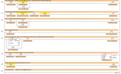
Lancie, I took your example of the Silo Exercise. I hope you don't mind.

I wanted to post it so that you could help me understand what exactly is going on in the routine because obviously, ladder logic isn't as straight forward as I thought. I have been told before that we must use the outputs to manipulate the inputs but apparently I'm not 100% sure what that actually means, or better yet how to set a routine up so that it works as expected.

I'm feeling kind of disappointed now because I thought I had it figured out.

LadderRungs_Silo_Lancie1.jpg
 
While the motor is off and the conveyor stopped, some other actions take place such as, a robot mills the said part. Now this is one of many issues I have right now.....while the belt is stopped, the motor off, the lamp off, and now the robot is done doing its job...I can not figure out how to start the motor back up.
To start the motor back up, use a "robot done milling" bit. When that bit goes from false to true (0 to 1), then restart the belt.
 
I have been told before that we must use the outputs to manipulate the inputs but apparently I'm not 100% sure what that actually means,. . .
What you really do is use the state of the inputs to determine when to turn on outputs (which in turn will cause some inputs to change). So your system or machine becomes a cycle, repeating actions over and over until a STOP button is pressed.

For the Silo exercise, start with Rung 2. With the Normally Closed Stop pushbutton not pressed, then when the N.O. Start PB is pressed, the System Run Mode bit will go on and seal itself on (until Stop is pressed).

From there, your best method is to load this program into LogixPro, and watch it run in the Silo Simulator. You can slow down the Scans rate until the action creeps along slow enough that you can watch each bit go on, and you can restart and repeat until you understand how it works. You can get a free copy of LogixPro at thelearningpit.com
 
Last edited:
Makes sense.

Ok, I noticed that on rung 000 of your SILO program that O:2/2 "system run mode" is the first condition of the routine. Then I see the "start/stop" conditions controlling O:2/2 on rung 002. Does this mean O:2/2 actually controls the sequence or is the program just set up that way? Apparently I'm still kind of confused how to set the conditions up to work properly when those conditions are used on other rungs throughout the program

I'm not sure if I am making sense with this question. I apologize if I'm not
 
Does this mean O:2/2 actually controls the sequence or is the program just set up that way?
Because the LogixPro simulator exercises are pre-defined, you have no choice about which Outputs to use for each motor or device. The O:2/2 output is actually the system RUN indicator, which is the same as a RUN relay or control relay that is ON when the system is in RUN mode. There is no particular reason it is on rung 2 instead of rung 0. It will work the same if you simply pick up rung 2 and move it up to be the new rung 0. In LogixPro and RSLogix, you can do exactly that. There are cases where the rung order does make a difference, but you want to strive for logic where the rung order does not change the operation or cause errors.

For 90% of your programs, you should start with a way to stop the system or machine (in addition to any external Emergency Stop buttons and relays). Until you get that set up and working, you don't want the machine to run. That usually means NC Stop and NO Start pushbuttons controlling a Run bit or Run light.
 
Last edited:
OK, I was curious about that. Sometimes I do find it a bit cumbersome to create a program different ways and test it with LogixPro because it is predefined.

I have a free copy of RSLogix 500 on my laptop with the emulator software. Maybe I should actually start using it instead since it is so close to the actual software. I believe I could learn more about the inner workings of the software without the limitations of LogixPro. But, I can still fall back on LogixPro for animated visuals.
 
Sometimes I do find it a bit cumbersome to create a program different ways and test it with LogixPro because it is predefined.
That only applies to the 8 pre-defined simulations. There is the LogixPro "I/O Simulator" where you can pick your own inputs and outputs and simulate an infinite variety of programs (as I have done on this site for years now).

The RSLogix emulator is a good tool to have. It is a little cumbersome in that you can't easily see the Input devices, Output devices, and the program logic all at the same time (as you can using the LogixPro I/O Simulator).
 
Last edited:
I wanted to post it so that you could help me understand what exactly is going on in the routine because obviously, ladder logic isn't as straight forward as I thought.
Sorry, maybe I did not give you the help you wanted with the Silo simulation. What would help the most? I can make a detailed description of what each rung is doing in the Silo Exercise 1 program, if that would help. (I say Exercise 1 that you posted, because the Silo simulation had 3 exercises, each one adding more requirements to the program.)
 

Similar Topics

Hello! I am considering purchasing admission into the online PLC Technician II course from George Brown College. Does anyone have any...
Replies
14
Views
10,927
Hi everyone Im looking to expand my knowledge on plc's. I have moderate knowledge right now. Im wondering if any one has heard of george brown...
Replies
1
Views
4,313
I'd like to hear from anyone who has taken the online PLC tech course offered at George Brown College. I have already searched past threads and...
Replies
2
Views
4,327
Anybody been thinking about buying their training software or taking the class? They say you dont need a electronics background but I'm not so...
Replies
11
Views
15,323
Have any of you gone through the George Brown on line PLC course? It looks like a certification course. Just looking for some input on this. The...
Replies
7
Views
4,338
Back
Top Bottom