Micrologix 1400 Data File Question....

JoseM

Member
Join Date
Jul 2011
Location
Texas
Posts
381
I will like to ask a question to anyone who has experience with Micrologix 1400. I'm working on the PLC code and I added the unit to the I/O configuration but here is where I'm confuse.

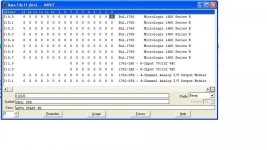
The processor I have is the 1766-L32AWA which comes with 20 AC inputs and 12 relay outputs. When I looked under the "Data File" for the inputs it shows I:0.0/0 .... 15 on the first line and there are various lines from I:0.1 .... I:0/7

I'm confuse because I don't understand how that relates to the 20 physical inputs on the 1400
 
On some Micologix 1400 units analog Inputs and Outputs are available.

Input words I:0.4,5,6 and 7 reflect the 4 analog input points.

Output words O:0.4 and 5 reflect the 2 analog outputs

Ignore the other points in the lower word which don't corespond to the inputs and outputs you know.
 
Last edited:
I:0.0/0 through /15 are the first 16 digital inputs. I:0.1/16 through /19 are the remaining four. As Bernie mentioned, the data files are set up to accommodate all variations of the 1400 and not all words will be used in your case.
 
Thank you for the reply. The 1766-L32AWA doesn't contain any analog input or outputs. Could you explain to me how the 20 physical inputs are going to be represented in the Data File.

Input Data File.jpg
 
Also keep in mind that you can use two types of addressing, bit or word.

As an example, here are your inputs with their equivalent 'bit' and 'word' addresses. It's up to you which method you prefer to use.

           Bit     Word
----- -------
Input 0 I:0/0 I:0.0/0
Input 1 I:0/1 I:0.0/1
Input 2 I:0/2 I:0.0/2
Input 3 I:0/3 I:0.0/3
Input 4 I:0/4 I:0.0/4
Input 5 I:0/5 I:0.0/5
Input 6 I:0/6 I:0.0/6
Input 7 I:0/7 I:0.0/7
Input 8 I:0/8 I:0.0/8
Input 9 I:0/9 I:0.0/9
Input 10 I:0/10 I:0.0/10
Input 11 I:0/11 I:0.0/11
Input 12 I:0/12 I:0.0/12
Input 13 I:0/13 I:0.0/13
Input 14 I:0/14 I:0.0/14
Input 15 I:0/15 I:0.0/15
Input 16 I:0/16 I:0.1/0
Input 17 I:0/17 I:0.1/1
Input 18 I:0/18 I:0.1/2
Input 19 I:0/19 I:0.1/3

Your local I/O are considered 'slot 0', so the input addresses will all start with I:0/... If you added additional I/O, those would get assigned as slot 1, slot 2, etc. and would be I:1/..., I:2/... etc.

🍻

-Eric
 
Thank you for the clarification. So, the data files are set to a standard configuration in order to work for the entire Micrologix family.
 
When you have a data file open, hover your mouse over each register. It should show you the equivalent 'bit' version of the address.

🍻

-ERic
 

Similar Topics

Hi Everyone, We have Silo System which has temperature sensor and these sensor data will be communicating through RTU unit to the Dedicated PC...
Replies
2
Views
608
On my plant there is a system with FT Historian SE 6.0. It is working fine. On other installataion there is a Micrologix 1400. Could anybody tell...
Replies
3
Views
1,667
Hi everyone, Brief overview of the issue: I have a CompactLogix (pt No:1769-L36ERM) that is connected to a MicroLogix 1400 (Pt no: 1766-L32BXB)...
Replies
9
Views
4,271
Hello there, I'm trying to send the state of a single internal bit (B3:3/8) of my main ML1400 PLC to a different ML1400 over Ethernet using the...
Replies
4
Views
1,751
Hi All, Can anyone help me out in reading the data from Micrologix 1400 PLC using JAVA programme through Ethernet/IP.?? or any java library for...
Replies
0
Views
2,614
Back
Top Bottom