Better way to monitor calculated force?

seth350

Member
Join Date
Jul 2011
Location
Over yonder
Posts
373
I have an application where a user is driving a servo to two absolute positions repeatedly in a back and forth motion using MC_MoveAbsolute. The user wants to be able to select a force limit from the HMI. Not torque, force.

The servo is connected to a 10:1 gearbox and then to a belted actuator.
The motor is an Omron R88-K40030H driven via an R88D-KN04H-E over Ethercat to an Omron NJ plc.

The motors rated torque is 1.3Nm or 11.5059696 in.lbs. The max momentary torque is 3.8Nm or 33.632832 in.lbs.

The servo motor’s software torque limit is set to defaults at 300%.

The 300% limit seems to correspond to the rated torque plus 300%, which is pretty dern close to the 3.8Nm.

This is what I did.
Max torque available at 300%:
33.632832in.lbs x 10:1 gearbox = 336.32832 in.lbs

Using the actual torque percentage value from the drive, I scaled it:
T = in:actTorque, x1:-300, x2:+300, y1:-336.32832in.lbs, y2:+336.32832in.lbs.

To convert rotational torque to force:
F = T/r
r = radius of belt actuator pulley
r= 1.758”

I then compare the calculated force against a limit. If the calculated force exceeds the limit for 100ms, a command is given MC_Stop.

We did some testing with load cells and the servo would stop but always seemingly at a lower limit than specified. We were using a load cell with a peak hold feature. I wasn’t sure how else to get it “spot on” and was wondering if you guys have done something like this or could provide some insight please.
Maybe my math is wrong? Scaling?
 
I'm not a mechanical engineer but, I think you have to factor in energy losses. Some of the torque converted to linear force is lost somewhere in the mechanical system, via belt stretch, frictions etc.
 
Yes, you are ignoring efficiency of your mechanics. You need to take into account the losses. Gearbox is probably about 93% efficient and belt is probably about 97% efficient. You should be able to get exact numbers from your suppliers.
 
Make sure your customer knows this is an estimation of force. Also, you haven't mentioned what controller you are using, but it might be possible to use MC_TorqueControl instead. That would be a velocity move instead of a positional move, though.
 
The controller is an Omron NJ301-1200 v1.07.
I had thought of using the torque control instruction, however driving to a position is more important than driving to a torque. They would just like to limit the torque during the move as close as possible.

I will see if I can dig up some efficiency ratings of this equipment and factor that in.
 
The controller is an Omron NJ301-1200 v1.07.
I had thought of using the torque control instruction, however driving to a position is more important than driving to a torque. They would just like to limit the torque during the move as close as possible.
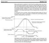
Limiting the torque should be easy but if the actual position falls behind the target position because of the torque limit, the integrator will wind up. There must be a means of prohibiting the position integrator from winding up while limited by torque.
 
Limiting the torque should be easy but if the actual position falls behind the target position because of the torque limit, the integrator will wind up. There must be a means of prohibiting the position integrator from winding up while limited by torque.

I believe I am seeing evidence of that Peter. Since yesterday, I have taken into account mechanical losses and have gotten “close”. The method we are checking it to confirm is not the most accurate. Using a hand held force gauge and physically pressing against the actuator until it limits and stops. The force gauge has a peak hold feature and so then the peak force is compared to the limit.
Throw the integrator windup in the the mix and we are even worse off.

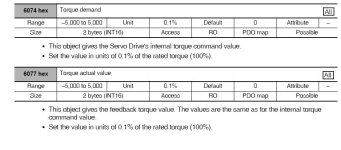
One thing I need to be certain of is what the units are for servo torque feedback. It seems to be in percentage, but not sure of what percentage it is.
100% = Max torque?
300% = Max torque?
100% = Rated torque?
 
Last edited:
The purpose is to move a test fixture back and forth a number of cycles and observe wear. If for some reason the test fixture gets in a bind, they would like for it to stop. Different test fixtures need different force limits. Depending on how gentle they would like to be.

I’m going to give the actuator manufacturer a call tomorrow to be sure I’m reading the correct spec sheet from their site. It’s a Macron Dynamics brand. There is one letter in the part number that is not matching up with their numbers.

Fundamentally, I think I have the calculation figured out.
I was not taking into account the gearbox eff, weight of actuator mechanics, and rolling resistance.
Adding the weight and rolling resistance together and divide by the pulley radius should give the torque required to just move the actuator.
That number should then be subtracted from the available torque from the motor.
(Tmax x 10:1 x 0.90) - torque to move actuator
That should give me torque available at the actuator, then divide that torque by the pulley radius to get force available at the actuator.
Correct?
 

Similar Topics

Good Afternoon , It seems like we always have problems with using Type J Thermocouples with our slip rings . Would using a RTD at 10...
Replies
6
Views
1,640
I am beginner in B&R Automation Studio and TIA Portal. Have an experience in electrical part of PLC cabinets. Now its time to get a new skills...
Replies
8
Views
1,670
Bla Bla Bla, why doesn't it work, l need help and l don't understand PLC's. Or better they understand everything, but can't understand +1 -1 = 6...
Replies
22
Views
6,005
I rarely need to add a network card to the drives we install... very rarely. But my sales-guy said he needs to quote a network-connected ACH580...
Replies
6
Views
2,589
I'm currently on a research project where I can send tag read & write requests to both SLC as well as CLX controllers. Presently, there's no...
Replies
8
Views
2,411
Back
Top Bottom