How to set up a dynamic data move in ladder?

Join Date
Dec 2017
Location
Upstate NY
Posts
18
I have been bashing my head up against this one for a while, so take some pity on me if I wind up coming off as very confused.

I have 4 tags containing the thickness of 4 shadows across a sensor, counted from left to right. "Sensor1.RawShadowThickness[0]" to "Sensor1.RawShadowThickness[3]" as a DINT. The shadows correspond to the thickness of wire being produced. The lowest numbered wire machine is on the left and increases by one to the right, ie: 1,2,3,4.

I am trying to figure out how I can "map" the shadow data to the wire. When all 4 wire machines are running it is a simple one-to-one map, however, if one machine goes down, and the line runs without a wire present the information becomes corrupted.

Say wire machine 2 is down, now there are 3 shadows instead of 4. Shadow one still corresponds to wire 1, but now shadow 2 corresponds to wire 3, and shadow 3 to wire 4. Every possibility of machines not drawing wire across the sensor must be accounted for.

I have a bit/bool for each machine that is high/true when the machine is drawing wire and low/false for when it is not and there is no shadow expected.

The only truth statements I can figure out is "Shadow 1 wire machine number = Lowest machine number drawing wire"

It is at this point that I lose my mind because I can not think of a way to process all possible occurrences.

Then the next issue rears its head:
How do I copy/move the data into the correct tag waiting for the wire thickness?

I'm really lost on this one. Please help!
 
Your logic will look something like this pseudo code:

Code:
x=0 //Number of valid wires found

if M1=1{    // Machine 1 is drawing wire
  wire1 := S1.RST[x]  //assign wire1 to the first sensor data
  x++  //increment x to the next element of the shadow array
}
if M2=1{    // Machine 2 is drawing wire
  wire1 := S1.RST[x]  //assign wire1 to the next sensor data
  x++  //increment x to the next element of the shadow array
}
if M3=1{    // Machine 3 is drawing wire
  wire1 := S1.RST[x]  //assign wire1 to the next sensor data
  x++  //increment x to the next element of the shadow array
}
if M4=1{    // Machine 4 is drawing wire
  wire1 := S1.RST[x]  //assign wire1 to the next sensor data
}
//x now represents the number of machines running

This is off the top of my head, so I might have not thought of something or missed something...
 
Last edited:
Maybe you could look at them as binary code. If you know which machine is drawing wire. Then map each machine bit to a DINT and map shadow sensors to another set of DINT bits. Depending on Machines running you DINT would = 0-15 and Shadow DINT would be the same.

M1=DINT.0
M2=DINT.1
M3=DINT.2
M4=DINT.3

Do you mean I should create a lookup table? I simplified the problem in my first post, the plant process consists of 6 wires and one sensor, so I would have to code all 63 possibilities, which seems rather brute-force, and I may just have to do that though...
 
I was thinking to map each machine and Shadow to a DINT bit. So, each machine and shadow would represent a binary number. 1,2,4,8,16,32. If all 6 machines are running then the DINT would equal 63. If your shadow detects all 6 it would equal 63. If your shadow always shifts then it sound like you would lose the 32 bit in shadow DINT and it would equal 31. So if you know how many machines are running then you should know what the shadow bits should equal. 4 machines running should always equal 15 on the shadow bits no matter which machine has stopped.
 
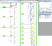
If the wires are always in the correct order, then the method I proposed will work. Here is what it looks like in Ladder Logic (Micrologix 1100 is what I had handy). I added the CLR statements at the end to blow away data for machines that are not running. EDIT: You first said four wires, then later cwal61 said six, so I went with six in the example. It might only be four now that I reread the thread.

sensorarraymap_000.png
 
Last edited:
EDIT: You first said four wires, then later cwal61 said six, so I went with six in the example. It might only be four now that I reread the thread.

No need to worry OkiePC, the actual application does have 6 wires, and yes, they are guided by rollers and sheaves, so there is no crossing or changing position. That would be the start of a whole different disaster!

I'm going to give this a deep look over and see if I can place it into practice!
 
Am I seeing things correctly OkiePC? Are you using X as a variable within the source parameter for the move instructions?

I was completely unaware that this was possible.
 
Am I seeing things correctly OkiePC? Are you using X as a variable within the source parameter for the move instructions?

I was completely unaware that this was possible.

Yes, it is an index of the array. I used N7:0 and gave it the symbol name "X", then I changed the view properties to show symbols only. That makes it look more like RSLogix5000. I couldn't get the "sensor array data" variable (N70:0 through N70:5) to look right with a symbol name, so that one still shows the Micrologix address.
 

Similar Topics

I am trying to use a MSG instruction inside a re-usable AOI. Any suggestions on how to set-up dynamic addressing for the MSG communication path...
Replies
4
Views
3,255
Omron AD081-V1 Analog Input Card Offset & Gain Adjustment Entering Adjustment Mode 1. Set the input card in adjustment mode (Turn ON Dip SW No-1)...
Replies
0
Views
54
I was loading a program onto an XE1e2 PLC and it got stuck on these two windows and won't progress. It won't let me connect from the PC to reload...
Replies
0
Views
62
Hi all, i have recieved some 4RF Aprisa SR+ ethernet radios from a customer to configure. Issue is that they are used and have non-default...
Replies
0
Views
65
I want to set user security level based on the value of a tag in my PLC called "ActiveUser". That tag will contain the A-P code which we use for...
Replies
6
Views
205
Back
Top Bottom