1746-NI8 Analog Input Module Question

sxj1988

Member
Join Date
Apr 2014
Location
Rochester, NY
Posts
38
Hi everyone,
I have a SLC 500 (5/04) with a 1746-NI8 Analog module input.
I have two questions:

1. I have noticed there is a IN0-, IN0+ and SHIELD PORTS. I am currently trying to wire a potentiometer in that module. Currently I have my potentiometer connected:

- Black wire (-) to the 10VDC power supply (0V)
- Red wire to the (10V)
- Signal Wire to the IN0+ Port (1746-IN8)
- The IN- port I have it connected to the 10VDC Power supply (0V)
- I am not sure where should I connect the SHIELD port to?
(Also my MODULE STATUS IS ON - GREEN however my CHANNEL STATUS are all OFF)

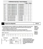
2. This question is about how to read the voltage (0-10Vdc) into the ladder logic program. I referred to the specification online and follow the programming configuration.

The application that I am trying to do is to have the potentiometer on a robot arm to read the positions for each joint.
Untitled.jpg
 
Thanks for the reply. (I am quite new when it comes to Analog components)
As for the potentiometer that I have it does not have drain wire. It has three wires (Negative, Positive, Signal).

As for the lights not being enabled, is it because I have wired the wrong ports?
 
the "drain wire" is part of the cable connecting the potentiometer to the analog module ... most of these cables have a "shield" made of tin foil wrapped around the conductors ... there's usually also an "extra" uninsulated wire inside the tin foil shield ... that uninsulated wire is usually called the "drain" wire ...

the basic idea is that any stray radiated voltage which the cable picks up (think of it as something like a radio antenna) will be trapped by the shield – and not transferred into the signal wires ... by connecting the drain wire correctly, you give the stray voltage an escape path from the shield ...

for the rest of your problems, we can give you MUCH more detailed help if you can post your ENTIRE project file (RSS extension) ... you'll have to zip the file first (forum rule) and then attach it to a post in this thread ...
 
I would recommend running a 3 wire shielded cable to your pot and clip and insulate shield and drain and pot side, shields should only be connected at plc end this is to disipate any voltage induced by nearby emf so as to not give you a faulty signal.

As for the lights the channels need to be enabled in the card configuration of plc software
 
I have configured the IO Configuration (on RSlogix500) for the analog module. Currently its located on slot 1.
Also I noticed there is a 1746-NI8 Class 1 and a Class 3. Any specific difference between these two classes?

I will find a 3-wires(with a drain wire)cable to connect to my potentionmeter onto the PLC analog module and provide an update once I connect it.
 
yeah it will work without shield that is more to save you from headaches in the future especially your analog signal is coming from or running near vfds.

and the not enabling channel thing is one of the biggest headaches along with not having your routine assigned to run with a JSR
 

Similar Topics

Trying to read analog inputs from 1746-NI8 card, but values show 0 and channel status LEDs never come on. Details: - SLC 5/05, 1747-L551...
Replies
6
Views
2,894
Wondering if anyone has seen this and possibly knows how to fix. We have an SLC 5/05 with an NI8 and an NI4 in slots 1 and 2 in the rack. Both...
Replies
2
Views
3,465
While this is fresh on my mind, let me pose a question which has me stumped. I have a SCL 5/03 16kM OS 302 Series C FRN 3-8 i.e. (1747-L532E)...
Replies
12
Views
6,558
Hi Folks I am wireing a 1746-NI8 analog card and I suspect the card is bad... unless I am missing something. I have the literature for the module...
Replies
3
Views
1,823
Hi, I have an analog input card on a slc 5/01. Im pretty sure everything is configured properly and the dip switches on the back are set to 4-20...
Replies
7
Views
2,129
Back
Top Bottom