Set Reset problem on 1 bit ?

userxyz

Member
Join Date
May 2002
Location
any
Posts
2,768
Hi Guys,

I'm having a weird problem that I don't understand.
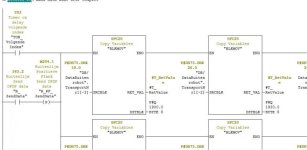
The problem is that a bit needs to be transferred via DP/DP coupler with a sensor event. The bit can be transferred a 100 times without issues and fails then one time, the failmoment is random and doen't happen often but is a big issue for the production.

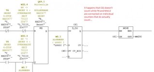
After making logs plc based (SCL and fifo tables) showed on WinCC I could see that the problem came from the sender PLC. So I started placing counters on every possible condition and action. The thing is that the cause is a Set Reset function.
1.jpg

It happens that C61 misses Q64.1 while it should be setted. I have counters on the T6 signal and M32.4 also, they both count ??? Ok the moment can be different... But that's impossible if you look at the next network. In this network we allready made it a RS instead of a SR just as a test and since then the problem didn't happen again...??
2.jpg

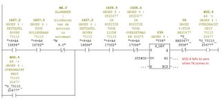
Here you can see that M32.4 is stopped by T6. T6 is a on delay timer from a sensor input. This network is processed later then the previous one, so the combination T6 + M32.4 should allways bin there. So still, why is it possible that C61 doesn't count sometimes ?

These are my counters on WinCC:

Knipsel.PNG

No data is used double, I've checked that many times allready, not in Scada, not on HMI's.

Any help is appruciated a lot,

Thanks,
Kind regards,
Gerry
 
The problem is not very clear for me as I can't see the entire sequence of the logic.

You said this:

In this network we allready made it a RS instead of a SR just as a test and since then the problem didn't happen again...??
Now, is the problem still happening with the RS instruction or not? Or was it only happening with the SR instruction?

You mentioned event as well... is all of this logic being called from OB1? Or is there any cyclic or error OB where these variables are used?

Do you see Q64.1 being set?

Another thing I thought of is that you are looking for a missing rising edge (missing pulse), but have you confirmed that this isn't caused by a missing falling edge (the previous pulse never reset)? It's strange, but it's a possibility.

Does T6 have a reset condition?

What is that M3.7 doing? Could that explain the difference of behavior in the M32.4 and T6? It is the only thing that bypasses the logic you are describing.

Edit:

Just checked up on it and the SR and RS instructions have another difference other than what is the dominant function. The SR flip flop will have the same value for the bit (Q64.1) and the Q output, whilst the RS flip flop has them inverted. Have a look at the examples here:

https://cache.industry.siemens.com/dl/files/822/45523822/att_82001/v1/s7kop__b.pdf page 25 onwards.
 
Last edited:
Sr

Hello,

Thanks for your reply.
With the SR the problem is there.
With the RS we are still evaluating, but until now no problems.
the first network is in FC33 and the second in FC40.
FC33 en FC40 are both called unconditionally in OB1.
When it happens Q64.1 is not Set.
T6 is a ODT connected to an I600.0 with 250ms delay.
the previous is reset for sure, because the other PLC checks this.
M3.4 is connected to a physical input, it's a manual switch for setting the bit manually. Can this be the cause, I think not because, it's on the SET connected.

It's a weird problem, in 15 years of programming never had such error :).

Thanks,
Kind regards


The problem is not very clear for me as I can't see the entire sequence of the logic.

You said this:


Now, is the problem still happening with the RS instruction or not? Or was it only happening with the SR instruction?

You mentioned event as well... is all of this logic being called from OB1? Or is there any cyclic or error OB where these variables are used?

Do you see Q64.1 being set?

Another thing I thought of is that you are looking for a missing rising edge (missing pulse), but have you confirmed that this isn't caused by a missing falling edge (the previous pulse never reset)? It's strange, but it's a possibility.

Does T6 have a reset condition?

What is that M3.7 doing? Could that explain the difference of behavior in the M32.4 and T6? It is the only thing that bypasses the logic you are describing.
 
Was this working before and only now started happening? Or has this always been like this?

What I find odd is that the conditions are related with something mechanical. T6 must be off for M32.4 to be set (and in this condition nothing happens with the flip flop, but then I600.0 and T6 must come on to trigger the flip flop.

In which rung is T6 located? If it's between the two screenshots that may cause some issues I think as the status of T6 will be different between calls to the rung.
 
Timer

Thank you for your help.

The first network is in FC33
T6 is written in FC40 NW20
The second network is in FC40 NW32

So yes, T6 is written in between. I don't understand why you see an issue in this ?
Could you explain that ?

Wait I understand, the status changes and is processed in NW32, before processing in FC33. the PLC cycle time is between 5 ms and 20ms. So if the status T6 changes les then the current cycle time, then NW32 will make the bit M32.4 false before it setted Q64.1. Is this what you mean ?


Kind regards,
G


Was this working before and only now started happening? Or has this always been like this?

What I find odd is that the conditions are related with something mechanical. T6 must be off for M32.4 to be set (and in this condition nothing happens with the flip flop, but then I600.0 and T6 must come on to trigger the flip flop.

In which rung is T6 located? If it's between the two screenshots that may cause some issues I think as the status of T6 will be different between calls to the rung.
 
Last edited:
Yes.
That was what I was thinking about. By having the timer in between the two instructions it is not guaranteed that the timer will have the same status in the same cycle.

I had something similar once with a partial process image that would randomly update an input in the middle of the code thus giving unreliable results and though this could be similar.

But it's just a guess...
 
Since you are transmitting a bit over profibus that means that there is a time component to this as well.

You could set and reset the bit a lot faster in the transmitting PLC than the receiving PLC can receive it.

The maximum frequency would depend on the bit rate of the profibus and maybe some other factors as well.
 
Last edited:
Copy T6 to an M flag and use the M flag instead. Timers update asynchronously to the program so can be in different states from one rung to another.
 
T6

Yes.
That was what I was thinking about. By having the timer in between the two instructions it is not guaranteed that the timer will have the same status in the same cycle.

I had something similar once with a partial process image that would randomly update an input in the middle of the code thus giving unreliable results and though this could be similar.

But it's just a guess...

I agree that the location of that Timer is not okay. But when the timer is setted, the M32.4 drops in that cycle and in the next cycle the send bit will bemissed in FC33, but it works in 99% of the cases, that's a liitle weird. I mean, T6 can only be 'true' after the first network, so in that case the first network will never Set the Q64.1 bit. Or how do you see this ?

Or wait, can the Timer elapse it's 250ms during the cycle on any spot in the program ?

Kind regards,
gerry
 
Last edited:
hi

Hi,

Could you see a reason or understand why the RS solved it ?

I understand what you mean. But the whole program is written with the usage of timers like this in conditions...

Kind regards,
Gerry


Copy T6 to an M flag and use the M flag instead. Timers update asynchronously to the program so can be in different states from one rung to another.
 
Last edited:
it started

Was this working before and only now started happening? Or has this always been like this?

What I find odd is that the conditions are related with something mechanical. T6 must be off for M32.4 to be set (and in this condition nothing happens with the flip flop, but then I600.0 and T6 must come on to trigger the flip flop.

In which rung is T6 located? If it's between the two screenshots that may cause some issues I think as the status of T6 will be different between calls to the rung.

It started happening after a collegue added some other code, maybe the cycle time changed by that...

kind regards,
Gerry
 
Other post

I've just red an other post here on PLCS about the S5 timers async.
I did not know that they are async.

I allways used S5 timers in such way:

A #Input
L S5T#5s
SD T1
A T1
= #Variable

Or like this:

--[#Input]----[SD T1 (S5T#5s)]-Q:= (#Variable)


So I never experienced this problem before, because I allways linked to a resultbit (that had to be processed).
But now I see that it is ugly programming to use async Timers in the logic on several places without using their output state.

Thanks,

We will try this.

Kind regards,
Gerry


Copy T6 to an M flag and use the M flag instead. Timers update asynchronously to the program so can be in different states from one rung to another.
 
Last edited:
Let us know the result. As I mentioned before, I think the timing of the input to the T6 and the location can affect result and in that 1% of the times cause what you see.

I'm not really sure why the RS instead of SR mitigated it though.
 
Async Timers

Hi Guys,

I think it's solved.
So I moved the timer to network 1 in FC33, before FC33 and FC40 are processed, the timer is evaluated and writes it's Q to M250.0. I replaced all timerconditions by M250.0. This way the timer is evaluated before the code and linked in PLC cycle to a bit memory. Never async anymore. And the problem didn't happen again.

The second problem I have is on a completely different unit and I think the problem is similar:

sss.jpg

Sometimes the data that is written to the other PLC is not right. The sourcedata is allways okay, but sometimes doubles and so on happens in the other PLC.

2 things I'm thinking to do:
- Timers again in network 1 before the code. Connecting timer to bit memory and replace timerconditions by bit memory.
- I'm also thinking to use SFC15 instead of the block moves, is it correct that these block moves can write data inconsistently to the other PLC ?

Thanks for your help guys,

Kind regards,
Combo
 

Similar Topics

I have problem with the B&R plc, which I think has gone to reset mode. The following photos give a general overview of communication and problems...
Replies
0
Views
1,670
I have problem with the B&R plc, which I think has gone to reset mode. The following photos give a general overview of communication and problems...
Replies
1
Views
1,743
I have problem with the B&R plc, which I think has gone to reset mode. The following photos give a general overview of communication and problems...
Replies
1
Views
2,183
I have problem with the B&R plc, which I think has gone to reset mode. The following photos give a general overview of communication and problems...
Replies
0
Views
1,379
Hi everyone, I'm having problems with the response time on my PID loop. I've tri.ed different tunnings but none have worked. In order to have my...
Replies
9
Views
2,866
Back
Top Bottom