Red Lion Flex Edge Modbus RTU problem

jcolley

Member
Join Date
Dec 2020
Location
Connecticut
Posts
3
Greetings all. First post here, new to RL, MODBUS, pretty much all things PLC, so please forgive me if I'm asking dumb questions.

- I need to use a DA50A Group 2 to convert MODBUS RTU RS 485 data over to an AB PLC with L5K.
- I have the DA50A configured to serial port 2, verified RS 485 settings, universal modbus master, end device at address 1, and correct addresses being polled.
- I see a periodic green LED flash on the DA50 port 2, but never a red LED indicating a receipt.
- I have the blocks created directly under the port 2 with timed rate of 500 msec.
- When scoping the RS 485 lines with a Picoscope set to serial decode MODBUS RTU, I see no transmission from master.
- When measuring A and B to ground with DVM, I do not see the expected 2.2ish VDC that I measure on any other modbus networks. Picocope A/B channels correlate this.
- I have tried throwing a 120ohm resistor on just to see, no change.

I am certain the the slave device is working, there is an existing master working that the DA50 will replace.

I have an email in to Red Lion for assistance, but feeling pretty dumb I can't get this working, figured I'd ask here for some ideas.

Thanks in advance for any advice.
 
There is no industry standard for labeling the 485 driver lines. Some vendors label the opposite of others. 485 should be A to A and B to B, or (+) to (+) and (-) to (-).

If the labels are backwards on one end, it won’t damage the drivers, but it’ll never work. Try swapping the driver lines on end and see if that’s the hang-up.
 
Welcome to the PLCTalk forum community !

You've got a pretty new product but a pretty old protocol for your first post. It's excellent that you've put a scope on the data lines and carefully worked the problem.

My reading of the DA50DA user manual is that it has one built-in RS-232 port and one built-in RS-485 port, both with RJ45 physical jacks. The bottom of the two serial ports is the RS-485 port.

Are you using "2 wire" RS-485 ? I presume you're following the wiring diagram in the user manual that shows that "TxA" and "TxB" are the Data A and Data B lines.

Do you have the Data Common (pin 6) connected between the FlexEdge and the slave device ?

When you measure "to ground" with your PicoScope, do you mean Pin 6, or the Chassis Ground ?

What is the slave device ?

What is your exact pinout of the cable between the devices ?

To my knowledge, Red Lion builds their RS485 stuff with high quality transceivers and uses an isolated port. If your slave device uses chassis ground for the reference and doesn't have a dedicated RS485 common wire, you'll probably have to connect Pin 6 to chassis ground on the slave.
 
There is no industry standard for labeling the 485 driver lines. Some vendors label the opposite of others. 485 should be A to A and B to B, or (+) to (+) and (-) to (-).

If the labels are backwards on one end, it won’t damage the drivers, but it’ll never work. Try swapping the driver lines on end and see if that’s the hang-up.

Thanks for the input. I have tried switching them and the red LED lights solid indicating reverse bus polarity.

Welcome to the PLCTalk forum community !

You've got a pretty new product but a pretty old protocol for your first post. It's excellent that you've put a scope on the data lines and carefully worked the problem.

My reading of the DA50DA user manual is that it has one built-in RS-232 port and one built-in RS-485 port, both with RJ45 physical jacks. The bottom of the two serial ports is the RS-485 port.

Are you using "2 wire" RS-485 ? I presume you're following the wiring diagram in the user manual that shows that "TxA" and "TxB" are the Data A and Data B lines.

Do you have the Data Common (pin 6) connected between the FlexEdge and the slave device ?

When you measure "to ground" with your PicoScope, do you mean Pin 6, or the Chassis Ground ?

What is the slave device ?

What is your exact pinout of the cable between the devices ?

To my knowledge, Red Lion builds their RS485 stuff with high quality transceivers and uses an isolated port. If your slave device uses chassis ground for the reference and doesn't have a dedicated RS485 common wire, you'll probably have to connect Pin 6 to chassis ground on the slave.


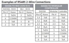
Hi Ken. Yes, there are two ports, but port 1 is RJ-11, port 2 RJ45. I am using port 2, selected to "2-wire". I had initially used pin 1 and 2 on the RJ 45 as shown on the left side of this drawing:
red lion 2 wire.JPG

Making things more confusing, today with Red Lion tech support, I was told to use "pins 1 and 8" (which makes sense to the right side of the pic) and that pins 1 and 2 were connected together internally" which doesn't make sense and I'm assuming was a typo. You bring up a good point though, I had not used the common on pin 6. The DIN terminal blocks the vendor provides for MODBUS connectivity have a ground block next to them, but it unused aside from it's internal grounding to the rail. I'll connect pin 6 there and see if that makes a difference.

I have two USB RS-485 cables that I can make connect, neither of which have a signal ground. I can get the two to talk to each other, but still cannot get the DA50 to read the one I have set as Slave address 1.

The device I'm supplying data from is an 800kw cogeneration plant produced in Czech Republic and using an engine from MWM with a proprietary (new) control system from MWM as well that controls both the engine and electrical distribution / grid control /etc. There is an existing device in there now as the Master that works, but we need to perform protocol conversion to the customer's SCADA system and that existing unit (national instruments) will be left in place for future development (disconnected).

I've tried a few different wiring configurations and still unable to get a receive LED or any indication of slave response on the picoscope.

I'm not certain however that I have the actual Crimson config correct however. It's attached if it helps as a .txt but is actually a .cd32
 
I don't know if the RJ11 is useable, but I would have looked to use it because it has the half duplex 485 pin B- on pin 5 and pin A+ on pin 4.

on the left side diagram, Pin 1 TxB and Pin 2 TxA are only half of what is needed for 4 wire 485, where are RxB and RxA? I don't get their designations.

The right side table makes sense with TxB jumpered to RxB (pins 1,4) and TxA jumpered to RxA (Pins 2, 3) assuming the only use is half duplex 485 because that's the jumpering scheme used when there's four terminals for 2-wire half duplex operation.

I agree, "pins 1 and 2 connected internally makes no sense", it shorts out the 485. Pins 1 and 4 connected internally does make sense, again assuming one never needs 4 wire 485.
 
In your first post you mention an existing master. Has this been taken off the network before you have tried the new master device, or are you bench testing this? As there can only be 1 master on a modbus network.
 
Also you need to make sure the baud, parity, stop and data bits are all the same as the network. And each device has a inique ID number
 
I agree that Red Lion tech support probably mis-stated something about the port pins.

Dan, I think the RJ12 on the FlexEdge is *only* for RS-232. The pinout table on the left is for connecting the FlexEdge RS485 port (RJ45) to an "RLC RJ11", which is probably on a G3 terminal.

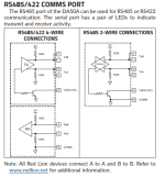
The schematic diagram on the same page is, I think, more useful.

The flashing of the indicator LED when the FlexEdge is transmitting, and the port red indicator when you reverse the wiring, both suggest that the RS485 transceivers and the project configuration are correct.

My thinking is that points to the lack of a common signal reference. RS485 signal amplitude is not measured A vs B, it's measured A vs Common minus B vs. Common.

Since the vendor ran their RS485 connection out to DIN rail terminals, you might have to follow those wires back and see if they failed to bring out the serial port's common wire.

The fact that there's a working Modbus master also gives you something to examine; go check out their wiring diagrams and actual wiring and see if they have an isolated common conductor.

FlexEdge485.PNG
 
Just to follow up with appreciation for the posts here. Solved the problem and the FlexEdge is working great now.

Two primary issues:
- Problem 1: I wasn't using signal ground on the Red Lion RJ45 port. That would have been immediately obvious if it weren't for problem 2.
- Problem 2: My dumb a** bought bulk generic RJ45 connectors on Amazon.
Result: https://photos.app.goo.gl/p7Tnbb2z795ojGrr9


New pass through crimpers and plugs on hand and problem solved.
 
Thank you very much for the follow-up.

And especially for illustrating how a connector can misbehave !
 
Just to follow up with appreciation for the posts here. Solved the problem and the FlexEdge is working great now.

Two primary issues:
- Problem 1: I wasn't using signal ground on the Red Lion RJ45 port. That would have been immediately obvious if it weren't for problem 2.
- Problem 2: My dumb a** bought bulk generic RJ45 connectors on Amazon.
Result: https://photos.app.goo.gl/p7Tnbb2z795ojGrr9


New pass through crimpers and plugs on hand and problem solved.

I am having similar issues. What exactly do you mean by "signal ground" on the RJ45???
 
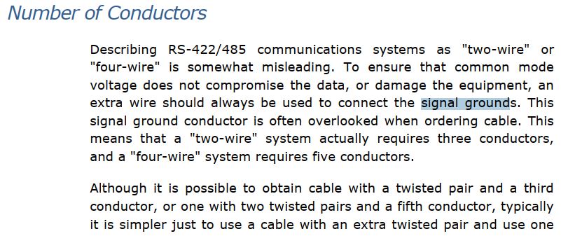
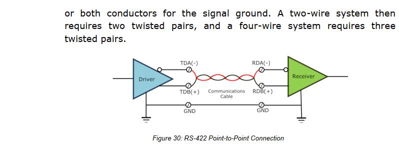
The term "2-wire RS-485' is a misnomer. It's really 2 driver lines wires and a signal ground.

The 485 differential signal is made by, as Ken points out, The voltage of the A driver line referenced to signal ground minus the voltage of the B driver line referenced to ground. Without a hard connection to the signal reference, whatever path connects is used.

Lots of vendors cheat in their implementation of RS-485 and only provide 2 terminals, one for each driver line, and omit a signal reference ground. In many cases it turns out that the signal reference is the case ground. That causes common mode problems when the case grounds of different 485 devices are at different 'ground' potentials.

Some vendor comments, first from B&B Electronics, the 2nd I can't recall.

B-and-B-Signal-ground-1.jpg

B-and-B-Signal-ground-2.jpg


grounding-needed-for-RS-485.jpg
 

Similar Topics

From the Red Lion website, after some customer enquiries in the last week or so... Rev. March 25, 2024 [18:30] Just thought it might help a...
Replies
9
Views
255
How do you install update on Red Lion Crimson ver 3.1. Do I just need to run the exe file on the host server?
Replies
1
Views
102
Hello All, I need the ability to remotely reboot a Red Lion CR3000 HMI. Due to some graphics issues when the database is updated the HMI must be...
Replies
4
Views
204
I'm trying to use a Red Lion Cub counter (Cub5B00) as a counter and give the cub's counts to a Graphite G12 PLC/HMI to display. After about an...
Replies
1
Views
107
Hi everybody, I have about three Red Lion HMI's, the calibration on the screens seems correct but where I'm using the pop up keypad to enter...
Replies
1
Views
111
Back
Top Bottom