New Year's puzzle (DrBitboy)

drbitboy

Lifetime Supporting Member
Join Date
Dec 2019
Location
Rochester, NY
Posts
8,029
Another relative velocity problem, but non-linear this time.

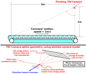
A quality control camera pivots (rotates) about a fixed axis to scan and inspect prints of a cat moving on, and with, a conveyor belt.

The camera is a TDI device (Note 1) with its rows parallel to the axis on which the camera rotates; the detector is the image plane.
To minimize TDI image smear, the rotation rate of the camera is varied such that, for the spot on the conveyor that is pointed to by the boresight at any given moment, the projection of that spot on the detector moves at the same speed and direction as the detector (row) charge transfer rate moves charge from row to row (refer to the TDI links in Note 1 below).

The camera is 1metre (1m) directly above the end of the conveyor; the start of the conveyor is 3m upstream of the end of the conveyor.

The focal length of the camera is 10mm; the pitch of pixel rows on the detector is 10rows/mm.

The image below is a rough visualization of the process using a pinhole camera model (Note 2); refer to Note 1 for details about TDI measurements.

One cycle comprises two scans:
1) at the start of the cycle the camera has its boresight pointing straight down at the end of the conveyor, and it starts and continues the first scan towards the conveyor start at a rotation rate that varies to minimize smear on the detector with a charge transfer rate of 7row/s;
2) when the boresight reaches the start of the conveyor (3m from the end), it instantaneously changes the detector charge transfer rate to 150row/s (Note 3) and reverses the rotation direction to scan back toward the end of the conveyor, again varying the rotation rate to minimize smear;
3) the second scan and the cycle end when the boresight reaches the end of the conveyor i.e. the boresight points straight down again.

To plus or minus one millisecond, how long does each cycle take?

Notes

1) TDI = Time Delay and Integration cf. https://en.wikipedia.org/wiki/Time_delay_and_integration and https://dokumen.tips/documents/drif...on-scanning-time-delay-readout-ccd-drift.html).
2) Pinhole camera model: cf. https://en.wikipedia.org/wiki/Pinhole_camera_model
3) The detector charge transfer is in the same direction for both scans.
4) Ignore second order effects e.g. the differing geometry of the rows offset from the boresight, the thickness of the cat prints, assume the pivot axis is equivalent to the pinhole of the pinhole camer model etc.
5) Now I need to go calculate the answer; it's possible there is a singularity that prevents a solution with the numbers provided.
6) I am curious what PeterN's MathCad will do with this, because there is an analytical solution.
7) I know this is not a realistic process.


Xmas_2020_puzzle_4.png
 
Bloody Hell ! that's a thesis !! I would not know where to start on this one ...
 
Bloody Hell ! that's a thesis !! I would not know where to start on this one ...
 
Update Ic


The problem definition has the detector charge transfer rates swapped, and the 7row/s rate is too low:

  1. When scanning the boresight upstream, i.e. from the end to the start, the charge transfer rate is 150row/s
  2. When scanning the boresight downstream, i.e. from the start to the end, the charge transfer rate is 99.5row/s.
Sorry for the confusion.


Update IIc

I found another bug in the problem statement; with the start point directly below the camera the analytical solution will fail on the second (downstream) scan.

So the start point should be 0.1m upstream from directly below the camera; so the camera scans from 0.1m to 3m, then from 3m to 0.1m.

N.B. "downstream" is with the conveyor motion; "upstream" is against the conveyor motion.
 
Last edited:
Forget about the downstream scan, I can't make it work.


How long is the upstream scan, from 0.1m to 3m, with a detector charge transfer rate of 150row/s?


Better yet: Mr. Melore, please delete this thread.
 
Update Ic


The problem definition has the detector charge transfer rates swapped, and the 7row/s rate is too low:

  1. When scanning the boresight upstream, i.e. from the end to the start, the charge transfer rate is 150row/s
  2. When scanning the boresight downstream, i.e. from the start to the end, the charge transfer rate is 99.5row/s.
Sorry for the confusion.


Update IIc

I found another bug in the problem statement; with the start point directly below the camera the analytical solution will fail on the second (downstream) scan.

So the start point should be 0.1m upstream from directly below the camera; so the camera scans from 0.1m to 3m, then from 3m to 0.1m.

N.B. "downstream" is with the conveyor motion; "upstream" is against the conveyor motion.
I was wondering about that. The upstream scans had to be much faster since the pictures would go out of view faster.


Am I to assume that each picture gets scanned only once?
If the camera is able to scan fast enough when scanning up stream then why move the camera at all. Just scan as the pictures go under the camera. The head doesn't need to move fast if the picture are 100 cm ( 4 inches in size then there are only 10 pictures. so at 1 m/s there is 100 ms to scan one image. Why don't we know the size of the images?


The focal length of the camera is 10mm; the pitch of pixel rows on the detector is 10rows/mm.
So at 1 meter each row row is 100 times bigger or 10 rows for 100mm or 1 row per 10mm.
Is the detector flat? That will add distortion at the edges of the sensor. It gets worse when scanning pictures at the beginning of the conveyor because the distance is worse (3.16m). If the camera needs to be moved it should move to scan one image at time as it move below to get better resolution.


There are too many questions but something doesn't seem right. The camera resolution isn't good enough. Is this a real project? The sawmill and veneer industry was doing much better years ago. This video is from around 2005. It used GPU cards to do the processing.

https://deltamotion.com/peter/Videos/Daqota Scanner-desktop.mp4


I use to write the optimizing and control programs for veneer optimizers in the early 80s.
 
I was wondering about that. The upstream scans had to be much faster since the pictures would go out of view faster.


Hmm, PeterN may be interested; perhaps he can help me fix this mess. Or maybe Mr. Melore will put this out of its misery.


The angular rate of a spot on the conveyor for a fixed, non-pivoting camera looking vertically down is the ratio of the [conveyor speed V=1m/s] to the [distance from camera M=1m], so angular rate = V/M = (1m/s)/(1m) = 1radian/s.


The angular rate of a spot for a fixed, non-pivoting camera looking at angle theta from vertical is [V/M (cos^2 theta)] (cosine squared); the hypotenuse of the right triangle [camera-end-start] is sqrt(1^2+3^2) = sqrt(10), so the [cos theta] there is 1/sqrt(10), and [cos^2 theta] is 1/10, so the angular rate at the start of the conveyor is 0.1radian/s.


The camera geometry is 0.01radian/row, so multiply that by the row transfer rate, rows/s to get the target radian/s at which the scene must "move" across the detector.


So 150row/s is 1.5radian/s on the detector, which is how fast the instantaneous scene needs to be seen to "move" across the detector. To accomplish this, the camera has to pivot (rotate the boresight) upstream against the conveyor motion, i.e. to initially add 0.5radian/s when looking vertically at the end of the conveyor, increasing to add 1.4radian/s at the start of the conveyor (end of the upstream scan), to maintain a constant 1.5radian/s of scene motion on the detector.


And 7row/s is 0.07radian/s on the detector, so the camera has to pivot downstream with the conveyor motion, i.e. to initially subtract 0.03radian/s at the start of the conveyor, increasing to subtract 0.93radian/s at the end of the conveyor, , to maintain a constant 0.07radian/s of any scene motion on the detector.


Am I to assume that each picture gets scanned only once?
If the camera is able to scan fast enough when scanning up stream then why move the camera at all. Just scan as the pictures go under the camera. The head doesn't need to move fast if the picture are 100 cm ( 4 inches in size then there are only 10 pictures. so at 1 m/s there is 100 ms to scan one image. Why don't we know the size of the images?


The number of rows in the camera is irrelevant to the puzzle because it is not a typical CCD two-dimensional image where all pixels are exposed at the same time.


As explained in the Notes, this is instead TDI imaging: it's like a line camera (one row of pixels read out continuously while the row scans over the scene); but with TDI imaging, there are multiple imaging rows of pixels, with the dynamics multiplexing each row of scene into each line over time, so the photons (light) from each row of scene are (is) integrated with itself only. The number of rows in the image is linear with the duration of each scan, which duration is the point of the puzzle.


So at 1 meter each row row is 100 times bigger or 10 rows for 100mm or 1 row per 10mm.


Yes, but that it is easier to work in radians/s.


Is the detector flat? That will add distortion at the edges of the sensor.


As explained in the Notes, ignore second order effects, specifically that one.


It gets worse when scanning pictures at the beginning of the conveyor because the distance is worse (3.16m). If the camera needs to be moved it should move to scan one image at time as it move below to get better resolution.


There are too many questions but something doesn't seem right. The camera resolution isn't good enough. Is this a real project?


Well, it does have "puzzle" in the title, and the notes specifically state that I know this is not a realistic process.


Other than swapping the rates, there is enough info in the problem statement.
 
A quality control camera pivots (rotates) about a fixed axis to scan and inspect prints of a cat moving on, and with, a conveyor belt.

7) I know this is not a realistic process.

Just for fun...

I DO know, you already find puzzle solution.

dθ / dt = d / (l * Δti) + V * cos(θ)^2 / L

d – distance between pixel rows (10^-4 m)
l - focal length (10^-2 m)
Δti - time delay of integration (1/150 s)
V – conveyor belt speed (-1 m/s)
L – vertical distance between camera and conveyor belt (1m)

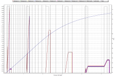
Please pay attention to attached picture

Description:
The conveyor belt moves towards the camera vision beam (i.e. belt and camera vision beam moves in opposite directions, that's why V = -1 m/s)
There are white stripes on the black conveyor belt (0.15-0.3 m; 1.15-1.3 m; 2.15-2.3 m; 3.15-3.3 m; 4.15-4, 3 m; 5.15-5.3 m - gray columns on the graph).
Vertical black lines – photon detectors refresh points
Starring row n – number of photons integrated by the detectors

This graph shows what camera vision beam linear speed (in relation to the conveyor belt) increases in proportion to Theta. That is why equal light areas accumulate (integrate) a different number of photons.

I.e. for practical application, it is necessary to multiply the accumulated(integrated) number of photons by the linear speed of the video camera vision beam (relative to the conveyor belt) or multiply Δti by the linear speed of the video camera vision beam (which, in my opinion, is more justified in the case of a spacecraft camera)

Cam_ConvBelt.png
 

Similar Topics

Hi I've inherited an IFIX 5.5 application. A picture is enabled every now and then. I beleive its being enabled by a tag that is read from a PLC...
Replies
0
Views
425
I have 15 wires coming from a black box sensor. I can't open it to look within. I know that two of those fifteen wires will comprise the feedback...
Replies
17
Views
7,668
Which wire would you cut, Red or green? Hint: You are color blind :yeah:
Replies
12
Views
4,045
Find 3 palindromic numbers that, when added together, make 85709 (Numbers are in Base 10) Answers by pm please.
Replies
19
Views
6,460
It was too early for Easter, suppose I could have done Chinese New year, but that's too close to Valentines Day. Two parts : 1. A Logix5000...
Replies
1
Views
1,310
Back
Top Bottom