Omron Plc

c_gunner

Member
Join Date
Feb 2004
Location
Detroit, Michigan
Posts
6
Well, it's the weekend and the electrical guys are off. I'm at work and I must wire an OMRON SSR. Please peruse my information and provide input if possible.

My application:

I am using a DC in / DC out Omron SSR (G3na-D210B). I also have an OMRON CPM1 PLC, an OMRON S82K 24V Power supply, and an external power supply.

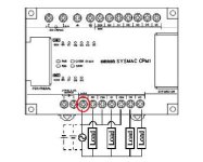
I am having a problem wiring the whole thing up. What I need to is figure out the paths my wires must take. I am using an output from the PLC (Output 010.03) to the coil side (or input) side of the SSR. The other side is wired directly to +24VDC (S82k Power Supply). On the Load side (Contact side) of the relay, I have wired 13.7VDC (external power supply) directly to the positive side of the relay. The negative side of the relay is wired to a solenoid and the other side of the solenoid goes back to the external power supply.

When I turn on the output, the SSR does not turn on. If I apply 24VDC direct to the SSR, it turns on (I eliminate the PLC from the loop). I assume I am backwards in my wiring, but not being an electrical genius I am afraid I'll blow an output or ruin this relic of a PLC we are using to run production. If possible, please confirm the wiring I described for the solenoid as well.

Many, many, many, thanks.....
c_gunner
 
Can you post a sample of your I/O wiring in a image, or code drawing?

On elevators we commonly wire inputs and outputs togeather to minimize field wiring to the call buttons. The button inputs and button light outputs are tied togeather in the controller panel, than only one signal wire exits the panel for each button & button light.

If this is what your talking about, post a drawing so we can see whats up.

Mike
 
elevmike- I do not have anything to scan with, the I/O wiring is really basic and the CPM1 is a shoebox PLC. It's just the output to the relay and the -24VDC to the other side. I appreciate your efforts and I wish I had a way to create an image for you to see.

Jay,
I have -24VDC to the "commons" on the outputs of the PLC. I am thinking that my wiring is wrong. What should I have the coil side of the relay wired to? One to the output and the other to -24VDC or +24VDC?

I did not see your image in the first viewing. Is there something like that for the OMRON SSR wiring? Omron tech support said they were sending me something yesterday and it never came.
 
hey, this is my first attempt to post on this site but it is the weekend and i'll try to help.
you should not have -24 vdc there is something possibly wrong with that reading, in the polarity. the common terminal should be the negative lead and the output to the coil of the relay. the other side of the coil should tie in to with the common discused earlier, this should allow the output to control the relay, if you need more help on how to make the relay turn on the ssr reply hope this helps - jason
 
c_gunner,

If I understand your question correctly, if your plc output common is +24vdc, than your plc input common would be -24vdc, or visa-versa. This would allow you to use an output do drive an input. However both inputs and outputs would operate from the same power supply.

It would look something like this..


+24vdc -24vdc (0)
* field wire *
| output 0 | input 0 |
*----+--||-----------*-------*-->|---+----* <input com
output | |
com | field wire |
| output 1 | input 1 |
+---||----------*-------*-->|---+


If this is what your talking about??

Good luck with it.

Mike
 
c_gunner said:
I have -24VDC to the "commons" on the outputs of the PLC.....What should I have the coil side of the relay wired to? One to the output and the other to -24VDC or +24VDC?

In case you're still fighting with this, the other should go to +24VDC.

beerchug

-Eric
 
I am still fighting this, but I am indebted to each of you who have taken the time to respond. I have successfully (with much help from you) made the SSR operable. Now I just need to get the wiring right for the solenoid. Unfortunately it is for an automotive application in which the connector for the solenoid has 13 wires. All I have is the wiring harness and no pin outs or diagram. But I am certain I get it now.

Jay- any chance you have pin numbers for the spec sheet you referred me to? I'd like to keep it for future reference. Thanks. Nevermind! Actually reading the material showed me the pinouts. Next time I will follow through more thoroughly to an attachment response.
Thanks again everyone.
 
Last edited:

Similar Topics

Hi There, I have couple of Omron PLCs connected on my kepserverex and my intouch reads data from kepserverex. I have been observing that roughly...
Replies
4
Views
83
I am working on a project using a NB screen and NX1P2 PLC. I am having a really hard time getting a real number to properly translate through to...
Replies
3
Views
116
Our plant manger/my boss wants each line to display the takt time above the line. I am trying to research the cheapest way to do this. Our plant...
Replies
3
Views
184
I have PLC Omron CJ2M with OD211 module. I want to use the pulse output and PWM output and this module. But i confuse how to activated this, i...
Replies
0
Views
93
I have a project to control the speed of motor DC using PWM Output on PLC and when im on working i have a several trouble and of of them is the...
Replies
6
Views
194
Back
Top Bottom