Siemens Rotary Servo In Torque Mode

JDCROCKETT724

Member
Join Date
Jun 2010
Location
Michigan
Posts
249
So here is my Siemens servo application. I am testing a part with two servos attached to it. One servo spins the part to different speeds while the other servo induces torque on the part. The torque needs to induce positive and negative torque depending on the test while on the fly.

I have a solution implemented that works, but I am wondering if I am over complicating it. My solution is to turn on torque limiting via the MC_TorqueLimiting block with the torque set to the test set point. Then to set the torque to either negative or positive I use a move velocity block with position controlled turned off to either drive the servo slower than the drive servo or faster than the drive servo. This creates a speed error that the drive attempts to correct by using torque that is limited.

The code works, but is there a better way? What would you do?
PLC is a 1500 and the servo drives are S120.
I am using telegrams 105 and 750.
 
That sounds pretty simple to me. Isn't that essentially the same way one would simultaneously control tension and line speed on a web?
 
I have not done a web application, but I have used something similar to this in press applications. Just curious if there was a way to simply command a torque positive or negative and get that reaction out of the motor without manipulating speed. That would be the simplest solution, but not sure if that is possible. Thanks for confirming my solution isn't out of the ball park.

Are there others out there that are simpler than what I provided?
 
Is the speed at which the part spins part of the test? Because keeping it from spinning at all (with a pair of vise grips or whatever), instead of driving it faster or slower with a second motor is the same thing, isn't it?
 
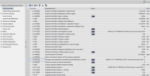
For S120 I write to parameter 1501 to switch between master(speed control) or slave (torque control) as required. I use a free telegram rather than 105/750


As you are using the Siemens telegrams I would stick with the scheme you have.
 
Last edited:
So here is my Siemens servo application. I am testing a part with two servos attached to it. One servo spins the part to different speeds while the other servo induces torque on the part. The torque needs to induce positive and negative torque depending on the test while on the fly.

I have a solution implemented that works, but I am wondering if I am over complicating it. My solution is to turn on torque limiting via the MC_TorqueLimiting block with the torque set to the test set point. Then to set the torque to either negative or positive I use a move velocity block with position controlled turned off to either drive the servo slower than the drive servo or faster than the drive servo. This creates a speed error that the drive attempts to correct by using torque that is limited.

The code works, but is there a better way? What would you do?
PLC is a 1500 and the servo drives are S120.
I am using telegrams 105 and 750.
Your method will work but it would respond to rapid changes because the integrator in the PIDs will need to ramp up or down and that takes time. If everything is pretty much steady state then go for it.


Yes, there are better ways but I don't really know what your are trying to do. I would look into using feed forwards. This reduces the dependency on the PIDs and their integrators.
 
The Siemens telegram is already configured to write to it - I don't know when it switches to torque control (maybe homing to a stop?)

1501.jpg
 
I wonder if I could simply write to the Q address of that PZD 1 for bit 14. Do you think that would work, or would my Telegram simply write over that command? Then I could keep my settings as they are now and be able to switch between speed and torque control when necessary.

This is a big project and Siemens is the one that has driven us down the path we are on. They explained to me that this path is not how it is typically done, but they believe it will work with the technology objects. Now I am wondering if they are using this project as a test to see if that is true.
 
If the servo that needs to generate torque for the test only needs to do that, then you could ditch the TO and control it yourself, but, as you said in your first post you had a working solution I'd stick with that.
 
So something I did not mention in my post was that, while I have it working, there are torque transducers on each motor that go to a high speed data acquisition system. The torque it sees has very fast torque ripple of about 30nm peak to peak. They want that smoothed out, and we believe it is the servos inducing this oscillation via its PID loops. Do you think torque control via P1501 would help smooth this out vs what I am doing?
 
So that I’m clear, you only use MC Move Velocity and MC TorqueLimiting on that axis? (Besides Stop, MC Reset of course )

If that’s the case then you could do what LD is alluding to and get rid of the TO for that axis and simplify
 
Last edited:

Similar Topics

Currently, I am using an old siemens encoder p/n:6fx2001-5ss24, 25bit, 10-30V with their own mating connector. SSI interface. Since the...
Replies
0
Views
2,880
Hi everyone, I am an omron plc tec , lately I came across a siemens s7 200 cn plc . Can someone help me regarding the software required and...
Replies
10
Views
106
This is the first time I am working with Simatic Manager Step7 as I started my siemens journey with TIA which is pretty easy and do a lot of stuff...
Replies
3
Views
83
Hi, I have PLC S7-1200 and switch XC-208 and Iam trying to implement this SNMP library: SIOS I am not sure, what I am doing wrong, but there is...
Replies
3
Views
99
Hi all, i am the new controls guy at the plant and i have inherited a pc from the previous controls guy with Siemens tia portal version 16 and 17...
Replies
17
Views
578
Back
Top Bottom