NEMA Standard Schematic Designations for Terminal Blocks

Jieve

Member
Join Date
Feb 2012
Location
USA
Posts
274
Hello, A couple of questions regarding NEMA schematics and terminal block labeling.


1) I am familiar with the DIN designations for components on an electrical schematic, =System+Location-Component:Terminal. What is the equivalent of this in use on NEMA schematics? I have seen "Component-Terminal" but this doesn't give any location or system info. I'm also not sure what to do when it comes to terminal blocks, hence the next question.


2) Say for example I have a set of 20x 2-level terminal blocks, one layer for 24V and the other for 0V, jumpered all the way across. The terminal blocks are labeled TB1000. How would you go about labeling the blocks themselves? Would you put number labels on each block or just +/- labels? Or both? Should they be labeled/ordered 1-20 or something else, considering that there are 2 layers?


3) If one wire is feeding all positive terminals of those 20 blocks, and the rest of the wires are outgoing from the blocks on both the top and the bottom (for convenience depending on location of the component they are feeding, giving essentially 39 supply terminals), how would I differentiate between the top/bottom + terminals on terminal block 18, for example, on a schematic? I have seen an example like TB1000-18.1/TB1000-18.2, where 18.1 was the top and 18.2 was the bottom, but I'm wondering if there is a standardized way of doing this. And this example doesn't work for multi-layer blocks, because nothing here is designating which layer I'm talking about. Is there a preferred way of doing this?


Thanks!
 
Please understand this is mostly from the Automotive view:

In the US, generally the terminal name is the same as the wire #. Then, terminals are generally put into numerical order. Any terminal numbers that are the same are generally understood to be jumpered together.

If I decided to name my wires '24V' and '0v', then my terminals would also be '24v' and '0v'. Any terminals on any terminal blocks with this number would be understood to be at the same potential and somehow connected with a wire or jumper.

Generally, wire numbers do not change through terminals. You could name them in order (1, 2, 3, etc) or use ladder designations which are usually the page + row:
1001 - page 1 row 00 wire 1,
1002 - page 1 row 00 wire 2,
2201 - page 2 row 20 wire 1, etc

I've never seen anyone in the US care about the specific pin # on the terminal strip (generally speaking) since they are all usually jumpered if they are identical.

As for the 'Top/Bottom' issue - I've seen two things personally. One is that all internal connections are typically on one side of the strip and all external on the other side. The other is that all OEM wiring is on one side of the terminal block and End-User wiring on the other side.
 
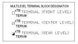
Using the multi-level terminal symbols on the attached file always worked well for me. The electricians doing the wiring always provided positive feedback and the wiring went well.

Also, I never referred to a multi-level terminal as top or bottom. Instead it is front, center, and rear level. Think about it: when looking at panel that is how a multi-level terminal it appears (front, center, & rear).

Using the wire number on these small, thin terminals is a challenge because, in my line of work the wire #'s might be 8 to 10 digits long. A number that long won't fit on the small terminal tab.

If we had 3 terminal strips they would be labeled as (1TB-1 thru 1TB-10, 2TB-1 thru 2TB-25, etc. All levels of a single 3-level terminal would be numbered 2TB-2 and the appropriate symbol shown.

Make sure you look at the attached file. It'll probably make more sense.

Terminal_Sym.JPG
 
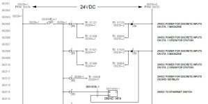
Attached is an example wiring diagram using the terminal symbols I described in my earlier post. Hopefully this helps clarify my example.

Terminal_wiring.JPG
 
Incredibly helpful information, thanks.

I've never seen anyone in the US care about the specific pin # on the terminal strip (generally speaking) since they are all usually jumpered if they are identical.
This is a little unintuitive to me, since for fast troubleshooting, replacement of sensors, etc. I would want to be able to look at a schematic and know exactly which + or 24V terminal block the component is connected to. How would I know this otherwise?

As for the 'Top/Bottom' issue - I've seen two things personally. One is that all internal connections are typically on one side of the strip and all external on the other side. The other is that all OEM wiring is on one side of the terminal block and End-User wiring on the other side.
Yeah in the EU I saw this as well and was told it is standard. But this seems also a bit inefficient with regard to panel space. When I need to distribute 24V and 0V to a bunch of internal components, using both sides of a set of term blocks for internal use gives me essentially double the number of terminals. For sensor terminal blocks I would definitely agree with this though.

Using the multi-level terminal symbols on the attached file always worked well for me. The electricians doing the wiring always provided positive feedback and the wiring went well.
Oh man, thanks for this! I have been looking at a schematic and didn't realize that the different square shadings for the different levels. BTW I've looked around to try to find a standard list of symbols for certain components (ironically terminal blocks being the main one), they are not included in any of the NEMA standards I've found. Can you recommend a good document for reference?

Also, I never referred to a multi-level terminal as top or bottom. Instead it is front, center, and rear level. Think about it: when looking at panel that is how a multi-level terminal it appears (front, center, & rear).
Good point on this, I recognized that issue as I wrote it but wasn't sure how to designate it better, will do it like this from now on.

Using the wire number on these small, thin terminals is a challenge because, in my line of work the wire #'s might be 8 to 10 digits long. A number that long won't fit on the small terminal tab.
Ok so it's common to have every terminal block in the cabinet to have a different number then? I've always seen things designated as, say PLC inputs for example, all TB1000-1 to TB1000-50, then a separate set of blocks (designated TB1001) where the PLC outputs might be TB1001-1 through TB1001-50. This seemed a bit more reasonable than ending up with wires with really long number designations, but I suppose tracing them in a large system would be way easier that way.

If we had 3 terminal strips they would be labeled as (1TB-1 thru 1TB-10, 2TB-1 thru 2TB-25, etc. All levels of a single 3-level terminal would be numbered 2TB-2 and the appropriate symbol shown.
OK so in my example the second level would be 2TB1000-3, for the 2nd level, 3rd terminal block of terminal block set TB1000?

Thanks!
 

Similar Topics

I have noticed that many HMI have a Nema rating of Mena 4/4X (indoor use only) Does anyone have any guesses as to what the constraints are that...
Replies
5
Views
1,799
Looking for some explanation/history between North American electrical symbols standards (how they relate, what are the latest, what is the...
Replies
3
Views
1,702
Good evening gentlemen, I am looking for VFD with NEMA 4x rating. It's a small one, single phase 208/230 input, 208 three phase motor 8.46 Amps...
Replies
11
Views
3,483
Hello, are there any standards for control wires naming rules? I have to set them up in my project (see pic). What is usually prefix and...
Replies
11
Views
2,235
Looking for a brief explanation for the NEMA MG-1 Part 31 standard for the actual voltage values. In reading many articles I have seen 1488Vp...
Replies
0
Views
1,402
Back
Top Bottom