Don't want an "S" curve..need a cosine curve

Hi Osmanmom! Long time no see. Ya know this is all your fault. You told me about LinMot linear motors .. then Peter twisted my arm to get his motion controllers ... would never have succeeded with out you two .. :)

This is just an experiment with some easily obtained Omron gear (eBay), to help me learn the science .. it's been hard .. I don't know anyone that works in machine automation .. I think I know how to do this .. and guidance will only come from an Omron engineer. There probably none on this forum .. and very few on the MrPLC forum ... and generally Omron support doesn't answer my emails .. and I know no distributors of Omron.

I've got some good suggestions here, and will post my solution when I have it.

By the way.. This thread does not notify me by email when someone posts a reply ... I've checked "Thread Tools" ... looks correct ... but doesn't work ... Basically, if you fail to select "notify by eMail" when you first post the thread .. you're screwed ....

Thanks for the info .. I'll write an ST program which will provide position data to Omron's "MC_MoveSyncAbsolute" .. that's basically what is happening in the making of the Random Sea... it is "brutal" :)

In the following video,
I first tried the Omron Nj with their G5 servo motor to see if it would run the Random Sea.. it did.. the LinMot is on EthernetIP .. An Omron engineer sent an example program for the E/IP, I added the HMI and another Omron engineer helped with the Random sea on EtherCAT

https://www.youtube.com/embed/BTCLrJuc01U?rel=0&controls=0&showinfo=0
 
Last edited:
To put it another way...

Wanted to explain the problem better:
Imagine this Sequence: A typical "S"curve ... generally starts from zero accelerates by a specified amount, then moves at a constant velocity until nearing the end point of the move, where it decelerates by a selected amount and stops at the "end point" .. a distant positive value. Then after a few seconds, another move, slower than the first slowly ramps at a constant speed back to zero... and, awaits the next move programmed and launched by a NA HMI

That sequence is what I'm trying to do.

In Ladder (Omron), you would probably use the MC_MoveAbsolute function block to make this move. Very easy, and almost intuitive...
default_smile.png


But.. what if that "curve has to be a "cosine wave"? It starts at zero and moves to the positive end position, and only the "path" is programmed, not the velocity or the acceleration.
Now you would probably use the MC_SincMoveAbsolute fb. And the "path" would be calculated in ST .. with the only inputs from the HMI as "Amplitude" and "Period". The final positive end position (amplitude), and the time (in seconds) it would take to get there. As we are not moving in a complete cycle, only a half cycle ... the "time" could be thought of as half the period.
This is some brute force programming, I cannot do .. yet
default_smile.png


I can generate a sin or cos routine in ST (With some help from Tyler Corbett):

(1) Pi:=3.141592;
(2) SampleTimeSec:=TOLREAL(TimeToNanoSec(GetMyTaskInterval()))*1e-9;
(3) SinTime:=ModReal(SinTime+SampleTimeSec, Period);
(4) FSin:=(Amplitude * SIN( 2 * Pi * SinTime/Period);
(5) Sine:= Sine + Fsine
The global variable Sine is sent to the Position input of the MC_SyncMoveAbsolute (or some Final_Move sequence in ST)

Now, The trick is to use 1/2 a Cosine wave (a 90 degree phase shift of a sine wave), and only use the first 180 degrees of the wave.. where it goes from zero to maximum positive (yes, it really goes from -1.0 to +1.0 .. but.. there will be an final rung for OFFSET (6) Final_Move:= Offset + Sine so that all moves are positive)

This equation must run only once, unlike the above example which would run forever. After doing that one move.. there is a time delay (TON) then the position ramps slowly back to zero .. and waits for another run.

I'm asking for any programming ideas that would control the equation for use of only a half cycle.. which starts at zero and moves positive to the input: Amplitude. I don't expect the actual program.. just some text explaining a good method to control the process. Please.

I assume the COS instruction would work just as well .. I just don't know how to use the best instructions to control the position equation...

Thanks Much, Regards, Michael
 
Last edited:
Imagine this Sequence: A typical "S"curve ... generally starts from zero accelerates by a specified amount, then moves at a constant velocity until nearing the end point of the move, where it decelerates by a selected amount and stops at the "end point" ..
This doesn't make sense.
It should say a s-curve starts at 0 acceleration and the acceleration increases as a function of the jerk until maximum acceleration is achieved. The motion may have a segment of constant acceleration before the negative jerk reduces the acceleration to 0 when maximum velocity is achieved.

I told you above. Start with the velocity as a function of the cosine and integrate it to get the position as a function of time. You also know the distance moved is 1/2 the peak velocity x time.

Peter .. I love ya.. but, you have to remember, I'm an idiot .. I wasn't always an idiot.. it started as I got older (I'm 76 now :) So ... It's not that I don't understand what you are saying .. I do .. I just don't know the "details' of how it implement it in ST

By the way .. a typical "S" curve in the non-"motion control" world, is just as i said .. a straight line move from A to B with a little acceleration at the start and deceleration at the end .. a line with some bends at each end... :) And, you know exactly the "details" of how that is done, which is vastly above my knowledge.

I understand I would get position if i integrate velocity as a function of the cosine .. but, I already have a working position equation, line (4) above: FSin:=(Amplitude * SIN( 2 * Pi * SinTime/Period);
It works fine .. but I need to start it at the right time.. and end it at the right time ... it must start and end at zero velocity, and maximum acceleration & deceleration.

My question is all about controlling that equation, making it start and end creating a curve similar to a typical "S" curve .. but is actually 1/2 of a Cosine curve ... I just don't know how to do that ... sniff!


PS: I'm still not getting email notifications when there are posts on this thread..
 
my brute force programming,maybe ok maybe KO

cos=angle(position SP)/angle increment(position PV)
= RESULT
= RESULT X position SP

velocity i guess constant

http://www.mathopenref.com/triggraphcosine.html

Thanks for the info Osmanmom .. The equation isn't the problem.. I should have been more specific ... My problem is managing the equation in ST or Ladder programming .. something most everyone here is well versed in.. 'cept me.

I'm imagining IF-THAN, and other expressions that will start and stop that equation's position feed to the "ME_SyncMoveAbsolute" function block which is talking to the LinMot drive via EtherCAT.

That's why I should be talking to Omron Engineers .. but Omron doesn't return my emails. and.. there are probably very few Omron engineers on this forum.

I have this post on MrPLC.Com's Omron section .. there have been no comments and only a few views. On this Forum, there have been many helpful comments.. and over 900 views!!!
 
Lamboom, i don't understand where there is a problem unless the Omron doesn't have a cosine move. If not use the cosine function to generate position every 10 ms and tell Omron to move to that position with move absolute commands. Make sure the accel and decel ramps are fairly fast.

If we didn't have a built in sine wave command I would have you do it that way or generate cam tables on the fly. You should be able to generate cam tables on the fly using the some of multiple cos() and sin() functions. Then down load them on-the-fly so the motion is seamless going from one cam table to another. You just need to make sure the next cam table starts where the last cam table ends.

You know what your real problem is.
 
This is all really confusing because I think no one is quite clear on what needs to be accomplished. Cosine is the same as sine to me, except for a phase shift. Sounds like you want to use a sine wave with an offset. The big question is are you trying to make your velocity look like a sine wave? If so, then that can be accomplished with the right accel, decel, and velocity values.
 
Hi Highland Controls:... This should help:

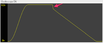
This is the move i would like to make driving the LinMot Linear motor (but without the glitch .. arrow) The first part is a cosine curve .. it's just a way of talking about a sin wave that starts and ends differently ... it's a phase thing. I should have just said it's a sine wave that starts at zero and moves to maximum .. peak to peak ..positive.. never goes negative 'cause of an offset. and stops there.. completing only 1/2 cycle. stays there for a while.. then moves back to zero in a slow ramp.

This move is amazingly easy to do with Delta's Motion Controller .. but, silly me, I'm trying to see if I can get Omron's NJ PLC to pull it off .. They give "complicated" a whole new dimension.

The problem is, I don't know enough ladder or ST programming to write the code that will control a working equation (4) shown above, that makes sine waves all day .. and have it just make 1/2 a curve cycle starting at zero and moving to a selected + amplitude in the correct time for the selected "period" of a sine wave. (cosine move ... :)

I think Peter's got something... will get back soon... still no email notices when someone post (over 1000 views! ... really!)

Tsunami_bmp.png
 
Peter

Omron can make sin and cos waves ... my little ST above shows that.. the trick is to control that equation with FROM-TO, IF-THAN's etc .. perhaps there would be 3 rungs in the ladder to do the Three part curve above. I'm starting to think I can figure this out. At this point I insert your comment:

"You know what your real problem is" I would do it using the forum's quote system.. but I can't figure that out either... the idea of inserting selected quotes then commenting on them, like you do .. is totally un-figureoutable .. I can quote your entire post ... but that's not classy ..

Actually, I have many many real problems.. which one(s) are you referring? :)
 
Lamboom, you are never clear about anything. Is that plot a plot of position or velocity?
Is that constant position or constant velocity section intentional? If so you need to segment you moves as shown in the pdf below.
Doesn't Omron have a trend like every other decent motion controller?

It looks like the Omron can generate a cosine curve .
You are approaching this all wrong.
You should first design you motion profile in Excel and plot it. Then translate the formulas to ST.
My Mathcad is like a free form spread sheet.

I included this pdf file showing how to do cosine ramps. It is complicated and may be of no use because I was only trying to simulate a point to point move with cosine ramps and there is a constant velocity section between the ramp up and ramp down. It is not the same as the sine start command on the RMC. My math starts with a more detailed version of what kvogel posted earlier, then like I said, all one needs to do is integrate velocity to get position and differentiate velocity to get acceleration. I don't know what else I can do?
http://deltamotion.com/peter/Mathcad/Mathcad - Cosine Ramps.pdf
 
"Lamboom, you are never clear about anything." (Ouch!)

"Is that plot a plot of position or velocity?
"

Thanks guys... it's all about position .. as a function of time .. the time to make a sine or cos wave (1/2 wave, actually)

The SyncMoveAbsolute Fb gets only "position" data ... every 1.0 ms, it will command the LinMot drive to go to that position. As an axis slave. the motor will move to that position with whatever it takes; however the drive might have some limitations on velocity or acceleration ability.. but, the LinMot can do about 50 meters/sec at very high acceleration. No input requirements for velocity or acceleration.

I get it.. Nice Pdf, Thanks ... I love your Cosine Ramps ..

Looks like a lotta math.. not sure I can run it in a 1.0ms CPU cycle ... this cosine curve doesn't have to be perfect, gravity and physics will compensate quickly for ****ty wave excitation .. but, that fix happens over distance .. an' I don't have much of that to work with .... tank is only 10 ft long now.. 20ft. long later. The tank in the Museum of Science & Industry (Chicago) is only 33 ft long.
 

Similar Topics

I have been reading everything I can find on the P_LLS the last 2 days but I am still having trouble understanding how the P_LLS swaps beyond 2...
Replies
9
Views
580
In OB1, I'm monitoring some values (first pic). The values are what I expect. At the same time, I'm monitoring the same values in the DB where...
Replies
1
Views
650
Maybe I am the last to know but Rockwell has put an EOL date on the 3 motion modules at the end of 2024 but maybe sooner. I know this will affect...
Replies
1
Views
962
On the laser displacement sensor now connected to my PLC, the manual says 4mA=643 and 20mA=64,877. However, I checked with a Fluke, injecting...
Replies
5
Views
888
I'm from a Mitsubishi Q-series background so excuse my ignorance. In Mitsubishi world, in my experience your Mbits (booleans) are just M1, M2...
Replies
20
Views
2,779
Back
Top Bottom