Constant Web Tension using VFD and PLC

raholter

Member
Join Date
Oct 2013
Location
alabama
Posts
8
I am working on maintaining constant web tension in the support liner for my material that is fed into my machine.

Background Info:
My material is feed into the machine via cassettes that store the material. In each cassette there are two rolls; a stock roll that stores the material after windup and a liner roll that stores the support liner during unwind. Each of these drives has independent motors that are controlled by their own VFD. The stock roll motor is speed controlled so as to have the same speed as the feed conveyors in the machine, while the liner roll is supposed to be torque controlled so that we can maintain constant tension during the unwind process to help with peeling the material from the liner.

I am able to calculate the speed for my stock roll at varying diameters to match the feed conveyors' linear speed but I am having trouble calculating the torque and speed of the liner roll to maintain constant tension.

Also, I think it might be important to note that the feed is not constant. The feed duration is maybe ten seconds long.

Any input will be greatly appreciated.
Thank you.
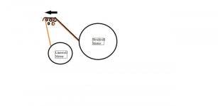
Cassette.jpg
 
Welcome to the Forum!
It is a matter or creating of a "dependency" between the Stockroll motor speed and the Linerroll motor torque by "connecting" the two VFDs in a Master-Slave relationship.
You will have to establish some sort of "gearing" between the Master (Stockroll) speed and the Slave (Linerroll) torque following a simple x=ay+b function where x=Linerroll Torque, y=Stockroll Speed, a=Slope and b=Offset.
Are the two VFD's fully integrated within your control system? (the Command/Reference and Status/Feedback are being handled via established communications)
If they are, then it is a matter of generating the Linerroll Motor Torque Reference as a function of the Stockroll motor speed feedback following the above mentioned first degree equation.
If the VFDs are not integrated and you are using I/O (hard wiring) controls, then you will have to configure one of the Master's (Stockroll) on-board Analog Outputs to "follow" its Output Frequency and then use this Analog signal as the Torque Reference for the Linerroll motor VFD while connected to one of the Slave VFD's on-board Analog inputs designated as the Torque Reference source while using the same function on either the Master's Analog Output or the Slave's Analog Input magnitude configurator.
 
Last edited:
The latter option could involve a PLC containg Analog Input and Output modules.
You could configure one of the Master Stockroll VFD's Analog Outputs to "follow" the VFD's Output Frequency, connect the VFDs Analog Output to one of the PLC's Analog Input module's channels, generate the "follower" function and then transfer the "result" to one of the PLC's Analog Output module's channels which is going to be connected to one of the Slave Linerroll VFD's Analog Inputs which is "designated" as the Torque Reference source.
 
Web control can be fun and challenging. You don't mention any feedback devices such as loadcells or dancers. Your task gets easier and control gets better if you can add feedback. In particular, a dancer not only adds feedback, but also provides a nice mechanical "constant tension" window of forgiveness.
 
The best tension controls I've seen have used dancers with variable air pressure creating force on the web and position feeback of the dancer creating an error signal. Tension controls objective is then to provide equilibrim or zero error on the dancer. Less demanding applications I've seen have managed to get away with load cells as feedback.
 
I have some experience in this area and as others have said tension control in webs can be fun but also frustrating. What drives are you using?
 
You may be able to use only the VFD's if you specify ones with optional wind/unwind software built into them. ABB would be one of those.
 
I've done something like that. Is the linerroll always 'unwind' and if it is why not put it on a variable dc clutch to control unwind tension. Mine uses an ultrasonic sensor to constantly measure the unwind roll diameter and ramp the unwind tension down (or up if you wanted) between two operator setpoints. The plc sends 4-20ma to the amplifier that sends 0-90vcd to the clutch. In our case, as the unwind roll reaches near core, the unwind tension automatically becomes less.
 
I'd just use VFD's with a some kind of tension sensor (Dancer arm, load cell, etc.). The Powerflex 70 series works great. I'm thinking you could have one drive be the "Master" where you have the tension sensor connected. Using the internal PID you could have the analog output on the master drive feed the analog input on the slave drive and regulate the speed.
 

Similar Topics

I am new to using Functional Block Diagram (FDB) language programming in CCW. I want to set a variable to a constant if a contact is closed...
Replies
7
Views
399
Hello all, this is my first time working with a PLC and dealing with hardware, so please have patience with me. I have an electric rod-style...
Replies
21
Views
3,015
Hello, I have posed a similar question before, but the DB then provided me with pre-allocated "spares". In this instance I need to declare a...
Replies
13
Views
4,114
Hello gentlemen, Why does this work: VAR CONSTANT SIZE_OF_dutEVENT : UDINT := SIZEOF (DUT_Event); MAX_SIZE_OF_dutEVENT : UDINT := 5...
Replies
2
Views
1,593
Hi! I know there is a lot of skilled people with Schneider somachine in this forum, so i have to ask something. How and why do you use constant...
Replies
4
Views
2,185
Back
Top Bottom