Further educating myself...

Davek0974

Member
Join Date
Nov 2014
Location
Hertfordshire, England
Posts
145
With the help of this forum, I had a plc replacement project signed off today, this is not my day job and haven't done plc stuff for about ten years, I re-used an AB SLC503 we had on the shelf.

The process was a step type printing one - Print, advance web, cut and repeat. There are options for the operator to just do the print alone or the advance, cut steps alone as well as various jog and batch control options.

The code was re-written as the first option was in-line and was becoming a bugger to debug. The newer version uses subroutines for each stage and the main ladder only has code for the cycle control, stop, start and safety monitor. Each subroutine is triggered by a latch and responds by triggering a latch when finished - this seemed to make a lot of sense to me.

The cycle control still had me playing for a while, today being a good example, I spent a few hours trying to figure out why a latch was not un-latching when the process was stopped at a certain point. It turned out it was unlatching but was immediately being re latched by another rung, it was just too fast to see.

Anyway it all worked out after a coffee:)

This got me to thinking of other ways to control cyclic machines - would a sequencer be better, easier? A counter maybe?

It's been a lot of fun so far, even more so as it works better now than it did when running on the original plc/program :) I have a possibility of three more to convert in the future.
 
Hi I always use the integer method for sequencers. Each step has a number and actions, and a complete.

It is like sfc chart but more basic

Step 0 - Wait for start
Start Pressed, Move 1 into Step register
Step 1 - Move material
Move complete, move 2 into Step register
Step 2 - Cut
Cut Complete, move 1 to do next move

You would need to add stop conditions and interlocking etc but you can get the general idea

For bigger machine you can add more sequencers and also have master/slave sequencers etc
 
Nice, I gather that would be using the MOV for the sequencing and the EQU as the trigger for each stage??

I would add an output register as well and then use a separate control section to set the input/start register and monitor the output/done register. This would allow me to easily gain access to each stage for manual triggering etc.

So for full auto it would simply run in sequence - (1s-1d)->(2s-2d)->(3s-3d)->(4s-4d) until the batch counter stops it at 4d or a soft-stop button is pressed where it would stop at any inter-step point but not inside a step.

Pretty similar to my current system using the dreaded latching bits ;) but with the bonus of only having to check/reset one or two bits instead of a hand-full of latched bits.

It's running now so I can code this sort of change at home and embed it when the next bug-fix download goes in.

Interesting stuff.
 
Thinking along, it wouldn't need a start and done register, just use more numbers.

0=idle
1=step 1 started
2=step 1 done
3=step 2 started
4=step 2 done

and so on, makes sense to me at least :)
 
Personally I would prefer that step 2 meant that step 2 was active, not that step 1 was done. Once you have accomplished everything you need to in step 1, simply have the last rung add 1 to the step index.
 
I prefer cjd's method for the step sequencer. I just did 2 machines, one that i hardly even understood how it was supposed to work. First i made an Excel step sequence chart that had steps across the columns and components i needed to activate in the rows. I colored in what components to energize during what steps. It made programming pretty simple since i used mainly LIM,GEQ,LEQ instructions. Plus when it got stuck in a step, i know exactly why it wasn't going to the next one. With latches/unlatches/etc, i think it would have been a troubleshooting nightmare. My 2 cents...
 
Hi
Your EQU and MOV is basically Allen Bradley language but yes.

I would add that I use a NEXT STEP Integer so at the to of the code I move NEXT_STEP into STEP and all step advance move the required step into NEXT_STEP

This stops 2 steps happening in a single scan which can be an issue depending on your code and I find waiting 1 scan for the next step to happen doesn't make any difference for my uses.

I agree with the_msp about keeping the step value as the true step otherwise would be confusing.

Typically I don't have a step complete, I just do the move into Next Step (Or Jump a Step or go back a Step)

But that should get you started at least

You can use the Step value to trigger messages on the HMI so you can track the process or show why the process is stuck/ what you need to advance the step
 
You're describing a simplified ladder-logic implementation of how Sequential Function Chart languages work.

I use these sort of State Machines extensively in sequential machines.

State 0 is always my "E-Stopped" state where nothing can run.

Numbers are cheap: my State values are always increments of 100 so that I have plenty of ability to put in "sub-states" if I need to.
 
Numbers are cheap: my State values are always increments of 100 so that I have plenty of ability to put in "sub-states" if I need to.

In my case "sub-states" are usually; OH-$4!7 I forgot to run the thingamabob that loads that third hopper!
 
Sfc style is old but the latest iec sfc software is expensive in most cases and the integer method is easily used in any brand plc.
 
Wow, some interesting stuff, not come across SFC etc yet, or state machines, more reading to do.

I like to view my logic (at least for this process) as a set of individual, separate steps. I have one set of a few rungs that controls the sequence of the process by issuing a start command then waiting for a done reply, then I decide which step I want next and again issue a start then wait for a done reply, and so on.

This is the second incarnation as the first was in-line and hard to debug. It's working fine now, but I know there are better ways and the learning curve is enjoyable. I chose latched bits as they suited my needs best but do come with a price tag.

I think changing to different methods is an educational exercise as it is working well, but that does not deter me.
 
Spent a few hours on the keyboard and have just about re-written my program using my version of integer step control.

I have attached a pdf of the main ladder file just to show my ideas and methods.

I used a "start" bit and a "done" bit for each stage as it meant i could control partial step requests easily, I couldn't see a way to do this without knowing exactly when each step is finished.

I have also removed all latched bits (i think) which should also help.

Will find out if it runs Monday ;)
 
It appears that Rung 26 will cause a full Stop after 60 seconds, whether the machine is idle or not. It seems there should be a XIO bit on Rung 26 that inhibits T4:13 if the machine is not idle. (Maybe you are periodically resetting T4:13 at other places in the program. If so, disregard this post).

The Stop sequence will go like this:
Rung 17: At Auto-Start, Bit B3:0/7 Pre-Start goes ON in Rung 17.
Rung 26: Bit B3:0/7 runs 60-second Timer T4:13.
Rung 27: After 60 seconds, T4:13/DN triggers B3:0/10.
Rung 17: XIO B3:0/10 opens, dropping out B3:0/7 AND T4:3/DN.
Rung 18: T4:3/DN goes OFF, whcich drops out B3:0/11 BIT_MC-START, stopping the machine.
 
Last edited:
Thanks Lancie1, I will check that out next time I have the laptop up, if you spotted that, I gather my style sort of makes sense :)

Does my "start" and "done" register make sense, in theory it does what I want it too.

What is the preferred way of reading ladder logic? I tend to read rung by rung but the plc does not run like that does it? From what I have read it scans the input bits, computes the rung logic, sets the output bits based on that and then activates the outputs accordingly?

I keep reading the comment "be aware of the scan cycle" but what exactly should I be aware of?
 
Yes, your style is okay. You might add more rung comments. Coming back to this program after a year or two, if you are like me, you will have forgot how it works and what each rung is supposed to do. Rung comments can save a lot of relearning time.

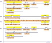
The PLC scans from top to bottom, left to right, unless there are special bits such as interrupts or immediate-execution bits. "Be aware of the scan cycle" usually means that it exists (unlike relay logic where every relay contact is "in" the circuit at every moment). In other words, PLC logic is generally sequential, so that the order of rungs can make a differece in how the logic is executed. Often, you can move a rung from one place to another and change the way the program works. This is true for logic that depends on a bit being true for only 1 PLC scan cycle (such as for one-shots and for alternator-type logic).

The attached picture illustrates that rung order makes a difference due to the existence of the scan cycle. These 4 rungs contain 2 identical alternator Outputs, except that the rung order is reversed for rungs 2 and 3.

In rung 0, Output 4 alternates On/Off each time the I:1/0 Pushbutton is pressed. In rung 3, Output 5 does not alternate (and does not turn on at all).

Scan Cycle- Rung Order MattersJPG.jpg
 
Last edited:

Similar Topics

Hi all, I'm working on a project monitoring DLR rings using explicit messaging - (Citect SCADA ABCLX driver + 1765-L62 v20.19) Just a few...
Replies
3
Views
1,261
I'm looking online in a Project trying to catch a Jam instant. I'm looking at the Logic of this AOI where I found the only instant of a Jam Photo...
Replies
16
Views
5,317
Hello, I am looking for a product to help me better understand logic control systems. I have been working with Allen Bradley PLCs for about 3...
Replies
5
Views
2,471
Hello, I have a question on furthering my education and what you guys think would prepare me for the future in automation. I have a 2yr diploma in...
Replies
11
Views
4,646
hi, my names Ben. Ive recently been thrown into the deep end of plcprogramming at work for large specialised vehicles. i dont know too much...
Replies
3
Views
2,835
Back
Top Bottom