PID Trainer, issue on setup

Wow! what we got here:
1. 30 posts
2. another pdf by Peter Nachtwey
3. Another mention from Peter Nachtwey about “real control experts”, about “solving” by approximation, using the Euler method without checking the original problem.

result:
1. the plant is 1/s^2 i.e. 2nd order integrator, i.e. unstable object of the 2nd order
2. An unstable 2nd order object is extremely sensitive to any dead band (mechanical, mathematical, algorithmic, etc.)

is it was'nt clear from 1-st post?

Oh yah! Don’t forget to spent next 30 posts to find THRORETICAL models poles
s^2+k*kd*s+kp*k = 0

Drbitboy, why do you use TF for SP, but not for disturbance?

it is obvious from the convulsions of the system in the video that there are huge "dead bands"
post 18. PIC 459 PIC 616 both not good - no process reaction to CV pitches = "dead bands"

Geniusintraining Continue to provide information so that it is as difficult as possible to understand it (curves to fit on 3 pixels, so that it was not clear the PID controller update time and the integration frequency of I-term etc)

Sorry but I have no idea what that is... I know just enough to be dangerous :)
Glad to meet a person with a great sense of humor, check out the joke:
the person building the PID trainer has no idea about control systems theory

Ouch! yeah! Peter, when you replace a metal ball with a ping pong ball, it's not about mass, it's about drag forces (air, friction, etc.), in real conditions drag forces for a ping pong ball are comparable to "gravity" are capable of both reducing speed and acceleration. And for this task, a differential equation in partial derivatives is required.
 
Wow! what we got here:
1. 30 posts
2. another pdf by Peter Nachtwey
3. Another mention from Peter Nachtwey about “real control experts”, about “solving” by approximation, using the Euler method without checking the original problem.
I used differential equations so I didn't need to make the assumption that sin(x) is close to x for small angles.
Yes, it system is second order. Notice that the tilt results in an acceleration, that gets integrated to velocity and that gets integrated to position. That is your two poles.
Yes, the mass cancels out.
I didn't mention Euler. i used Runge-Kutta to solve the non-linear differential equations.

So where was your solution?
 
OK now without emotions.

For the theoretical system (disturbance closed loop)
W(s) = k / (s^2+k*kd*s+kp*k)
kp = stability margin ^2 / k
kd = 2 * stability margin / k

However, as we can see, the behavior of the process is far from theoretical (significant "dead bands" mechanical, mathematical, etc.). Even after "tightening the nuts" some deadbands will remain.

To get a mathematical model, we can identify all "dead bands" (which, in my opinion, is practically impossible) and get a mathematical model that will be extremely complex, or approximate the process model using high-resolution curves, which is easier, but in any case, to "compensate" "dead bands", the model will have high order and/or dead times. For theoretical compensation of such a model, a controller with a high order of derivatives is required.

So I have a question: what is the PID trainer intended for? I mean typical PID-tuning methods possibly will be not good enough

Anyway let's "tightening the nuts", get high-resolution curves and information about PID-tuning parameters, scaling etc. and see what we can do


I didn't mention Euler. i used Runge-Kutta to solve the non-linear differential equations.

Who first described the approach and limitations of the family of methods?

So where was your solution?

Solution of what? geniusintraining's issue? I have not (either you) because of lack information.
Curve of an ideal closed loop for controlling the position of a hollow sphere on an inclined plane with a PD controller? How should it help to solve geniusintraining's issue?
 
Last edited:
I replaced that with a bolt yesterday but I noticed the other also had a little slop, great idea about the rubber band

Rubber band worked great and took out the slop on the lower linkage... working on other things this AM (got to pay the bills) I will update once I get back on this project

MaxK said:
check out the joke:
the person building the PID trainer has no idea about control systems theory

Take a chill pill Max.... and yes thats how the world works, have you ever worked on a car? or a piece of equipment? and thought "why did they make it like this?" the reason I made the post in the first place was to get others opinions and how to make it better, I built my business on the thoughts of the members here and so far its worked out pretty good.

MaxK said:
So I have a question: what is the PID trainer intended for? I mean typical PID-tuning methods possibly will be not good enough

For techs/students/bubba's to experiment and learn, if it was easy what would be the point? And yes I dont want to just plug in a loop and it work, I want people to have to work at it.

It may not be possible to make it work... this is something that I need to figure out and the point of the thread.
 
I think it's a good idea for trainers, probably not be able to simulate a real process & expect it to work, however, I built two systems, one was a simple heating element with a coil & water flowing in & out of a tank, the idea was based on an existing hot water supply so in effect, the tank held water, this was heated to a temperature of 98 Deg C., the top up was with cold water injected into the control loop, this obviously caused quite a disturbance , our technicians enjoyed playing with it, although they were not technically minded, by trial & error they learned how to overcome the problems by trying different settings & what parameters they needed to alter to tune the loop, the other was a simple heatsink & heater element, to enhance it's ability, there was a fan that could be varied to give different scenario's, this gave the techs a good start in tuning our CIP systems loops.
 
For techs/students/bubba's to experiment and learn, if it was easy what would be the point? And yes I dont want to just plug in a loop and it work, I want people to have to work at it.

Maybe it makes sense to think about tunable backlashes in the PID trainer?

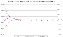
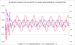
Just to show how "dead bands" can ruin a system...
1st graph - almost theoretical system (minor "dead bands")
2nd graph - significant "dead bands"

SP (t=0) = 0,01
SP (t=0,01) = 0
PD-controller

I2o_T.png I2o_R.png
 
Calbrate the bloody thing

I just realized what to do with the Feed forward/bias: use it to eliminate the Integral term:

  1. Assign a value of 0 (zero) to TI
  2. Fiddle with KC and TD until the system can stop the ball in a reasonably short amount of time
    1. Do not be concerned about where the ball stops, because
  3. The point is to find the output CV that makes the beam level,
    1. and the easiest way to know that the beam is level is to set the beam such that the ball is not moving.
  4. So make disturbances (poke or blow at the ball), and note the final CV each time the ball stops
    1. There might be noise in those final CV values, because of (rolling?) friction, irregularities in the channel, etc.
    2. but you should get a rough idea and an average of a few dozen values should be good enough.
  5. Use that calibrated CV-when-level value as the Feed forward bias (FFB) value, and TI will no longer be needed.
    1. Because with TI = 0,
    2. any time the ball is away from the setpoint and stopped,
    3. the Error will be non-zero,
    4. the output CV will be KC * Error + FFB,
    5. which will place the beam at an offset from level that should move the ball back toward the setpoint.
Increasing the available precision would be useful here as well: the input range of the PID PV and SP could be as large as 0-16383, and the same for the output CV range, although I suspect the position sensor and the servo do not have that many usable discrete positions.
 
Last edited:
Maybe it makes sense to think about tunable backlashes in the PID trainer?


I think the biggest backlash/deadband problem is the static friction that needs to be overcome to start a stopped ball moving.

  • A plastic ball on plastic channel isn't great, but it's better than cloth
  • A more obtuse angle in the channel might help as well,
    • or maybe use a piece of PVC pipe as the channel, so there is only one point of contact with a lower loading
  • I initially thought a hollow ball might better than a solid ball of the same material
    • Hollow ball acceleration coefficient is 5/3
    • Solid ball acceleration coefficient is 7/5
    • But I an not sure either of those is relevant to overcoming static friction
 
Last edited:
We need neither Runge-Kutta nor Euler for the model: a linear characteristic in time with a maximum radian/s for the servo-angle dynamics should be adequate; the double integration to model position is analytical whether linear-in-time angle or sine of same is used to calculate force and acceleration; the PID is discrete.

Some deadband dynamics due to friction could probably be added as well.

But that is irrelevant to @gitintraining's exercise. The real task is to find the various problems in the mechanics. The rubber band allows quantifying any effect of backlash. Improving input and output resolutions might help. Maybe a steel ball would improve the ratio of static friction to [k g sinθ] force for θ near zero. What about noise and sample rate in the position sensor measurement?

I suspect every time the largest boulder blocking the path is removed, two smaller will be found behind it.
 
Last edited:
Another way to calibrate would be to assign an a priori Feed forward bias, send the servo that value, and adjust the base orientation with washers or screws, counting turns either way until the ball is halfway between both directions' release points from static friction.
 
Adding a temporal sine wave (or saw tooth) offset to the Feed forward bias might be a way to minimize any response deadband due to static friction. Frequency of the offset should be different from any natural frequencies of the controlled system.
 
Gravity could replace the rubber band

Another way to eliminate linkage deadband would be to put the fulcrum at one end instead of in the middle, and the servo at the other end. The weight of the beam would keep the linkage length more or less constant as long as the beam is not bounced by servo steps.

This also cleans up the wiring to the position sensor (at the fulcrum).
 
Last edited:
Something has been bugging me about the video from Post #1. The startup angle, which I thought was due to static friction, seems be be steeper at the ends: after the ball hits a stop, especially on the right side of the image, it seems like it takes a bit more right-to-left downslope to get the ball moving left again.

I think there are two effects here:

  • Residual angular momentum after the ball hits the stop; this can be seen during seconds 0:06, 0:07, and 0:08 of the video, where the ball seems to roll uphill after hitting the stop.
  • perhaps the angle channel is deformed and bent a at the ends where it is attached to the stop: if the angle was wider, it might create a slight gravitational well near the stop; this can perhaps be seen during seconds 0:36 and 0:37.
 
Last edited:

Similar Topics

I have Real PLC but I dont have a real system to have PID Control- any recommendation how can I build such a system- there are some PID trainer...
Replies
6
Views
3,098
I've built a little trainer with a Automation Direct DL05, some pilot lights, switches, a ethernet card and some of the new PX remote I\O. The PX...
Replies
7
Views
4,230
Hi, I would like to assemble a simulator/practice booster pump system that uses PID to maintain steady water pressure under various outlet demands...
Replies
0
Views
80
Hello, I have a motor that we are sending a RPM Speed Output from 0-100% to the VFD. However, the Motor HP needs to be limited to 6000 HP and the...
Replies
3
Views
91
I have S7 1512C controler for controlling 48 PID temperature loop, the output is PWM. Please I need the best, most efficient way to write the...
Replies
13
Views
604
Back
Top Bottom