Ron Beaufort
Lifetime Supporting Member
I've just picked up a nifty new tool that might be interesting to some of our readers ...
background ...
last week I had a couple of students coming in who not only needed a five-day course on SLC-5/04 systems – but were also desperate for some basic-level training in motion control ... oops! ... motion control is something that I hadn't dealt with in over 15 years – and I had ZERO hardware in my lab equipment to put together any hands-on lab experiments for these guys ...
I easily found enough stuff on eBay to take care of the PLC end of the rope – a 1746-HSRV Servo Control Module; a 1746-HT Termination Panel; and a 1746-HCA Cable ... all together about $250 ... no problems – yet ...
but ...
I still needed some type of "motor" - and a suitable "drive" – and a suitable "encoder" ... trying to get all of THOSE pieces of the puzzle matched up and pulled together quickly became both challenging – and expensive ...
the point of this post:
I called up a friend of mine (Tim at TWControls) hoping that he'd have some spare gear lying around that I could borrow for a few weeks ... turned out he had a perfect solution to my problem – available for sale for about $70 – a Servo Axis Simulator ...
https://www.theautomationstore.com/...age_images.tpl&option=com_virtuemart&Itemid=2
this dandy little item is about the size of a BIC lighter – and it pretends that it's a drive, a motor, and an encoder ...
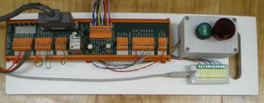
within an hour or so in the workshop I had everything that I needed neatly mounted on a breadboard - and wired up ... then I burned some midnight oil to work through some experiments on my own – and was able to pull together enough "motion control" material to make my customers very happy with the results ...
true – we didn't need to get into "torque" and "acceleration" and topics like that – but that's not what they were interested in anyway ... basically they just needed an understanding of how their existing SLC-5/04 programs use all of those mysterious "COPY" rungs to control the movements of their servo axes ... in their plant troubleshooting this type of stuff had always required outside contractors – and now they have enough understanding to start tackling some of that work on their own ...
suggestion:
if you're interested in this subject, I highly recommend that you start by programming in the sample rungs located at the back of Allen-Bradley's user manual for the 1746-HSVR module (linked below) ... these are uncommonly good examples – and (with the hardware available) I was able to make the little simulated axis tool perform all of the different types of moves that we needed to cover in the class ...
http://literature.rockwellautomation.com/idc/groups/literature/documents/um/1746-um613_-en-p.pdf
shown below is the breadboard arrangement with the Servo Axis Simulator connected to the 1746-HT Termination Panel ...
continued in next post ...
.


