Unexplained -NaN in Micrologix controller

Tim James

Member
Join Date
Mar 2012
Location
Texas
Posts
92
I have already searched the Rockwell Knowledgebase and looked through the Micrologix Instruction Set Manual and so far I can't explain this anomaly. I'm wondering if anyone else might have encountered it.

I have this program running on over 100 pieces of equipment out in the field and I have never seen this happen before. The fault occurred because F8:2 was assigned an indeterminate value. In this program, F8:2 (which is an PV in engineering units) is used only twice: once in an SCP instruction where it is written based off an analog input, and once in an LES instruction where it is only read. Other than that it is displayed in the HMI but is not written to.

NAN_SCP_FAULT_zpsc7200291.jpg


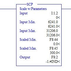
The Scaled Min and Scaled Max values, F8:44 and F8:45 respectively can be written to in the HMI and are not used anywhere else in the controller logic. I have already suspected a hardware error and after swapping the ML1200 controller and 1762-IF4 module with new ones, the problem re-occurred. It would seem that clearing out the NaN from F8:2 by writing a value to it manually via PC and clearing the fault will allow the controller to run for a couple of days before it faults again with the same problem.

Has anyone seen anything like this or have any ideas on the matter? Based on what I've read the only way the output of an SCP instruction is assigned a NaN status is (from the Micrologix instruction set manual:
If Input max - Input min = 0 and Input does not equal Input min, The Result becomes a negative overflow (for integer values) or a negative NAN (for floating point values)

or

If any of the parameters (except Output) are NAN (not a number), Infinity, or De-normalized; then the result is -NAN.

or

If Scaled max - Scaled min or Input max - Input min result in an overflow, then the result is -NAN


Given the values in the SCP instruction at the time of the fault, I don't see any of these criteria applying to my situation. I don't see anything in the instruction set manual or knowledgbase specific to indeterminate values on floating points, just NaN's in general.

The fact that this can be cleared and run for a period time before faulting for the same reason leads me to believe something is happening with the raw input from the analog in module causing the input parameter in the SCP to go to infinity or NaN, but considering I've replaced the analog input module already, I'm stumped. Is there anyway I can put a NaN logic trap in place to keep the controller from faulting if I can't identify the cause of the situation? Thanks in advance.


I think it has to do with the fact that your Input value is outside the Input Min. - Input Max. range. I would add a couple of rungs to make sure this doesn't happen.

Just my two cents.

Kind regards,
 
You must of screwed up big time NaN means not a numnber. It looks like you are trying to scale an digital 4-20ma input into an output of 0-300. I don't see why this should happen. I can see getting an error for being outside your input range. I did notice that your input range is in floating point where the input is an integer. Maybe that is it.
 
Neither of these thing should be an issue. In this controller the SCP function just continues to scale even if your input is below the minimum value. It really should be called the 'lower range' value. So in this example the output should be -75 which is what I would see if I didn't have a transmitter/transducer wired into the input (0 mA). As far as the input being INT and the parameters being REAL, the SCP function automatically treats all parameters as REAL values if the output is REAL. Like I said, I have 100+ controllers running this program in the field and 400+ other controllers running programs that use this same SCP scaling for transmitters to engineering values. I appreciate the input though (no pun intended)
 
Do you have any indexed or indirect addressing or any COP instructions writing to any F8 addresses?
What about to N7 addresses near the end of your N7 file?
IIRC the ML will let you overrun a file boundary.

Something somewhere is writing a value that is not a valid IEEE float. Is the HMI tag for F8:2 set as read only?

If you can zip the program and post it we might be able to help. Also, what HMI are you using?
 
Two different HMIs are being used depending on the circumstance, but in this particular case it's a AB Component 400. The tag in the HMI is set to read/write just because I generally set all the tags that way, but there is no writing object in the HMI application.

In terms of COP instructions or MOV or any file handling, there is a ladder file full of MOV and SCP instructions to setup MODBUS registers (setup as N9) for field comms. Included in the communicated values is F8:2, which is handled via a SCP instruction to output the engineering units value to an INT file (within the MODBUS register) with an added decimal point of precision. So 31.325 gets scaled to 313 and moved to the N9 file. Even if the DCS were to try and write a value to the N9 address, it would be overwritten via the SCP instruction so nothing but the analog in SCP instruction is writing to F8:2. As for the end of the N7 file there is something odd I just noticed. This must have been added by my programmer colleague because it's not my doing but there is a MOV instruction forcing '0' to the last address in N7 (N7:200). N7:200 is otherwise unused.

It seems like in terms of overrun a problem at the end of the N7 file would more likely effect F8:0, but I would be lying if I said I was intimately familiar with the memory space and usage on the controller.

It seems like even if the raw input to the SCP instruction went wonky, the controller would fault and it would capture that wonky value. I'd have to check to be sure but I'm pretty sure a faulted controller will not update it's input file based on physical signals. If that is the case, then I think you may be onto something with a possible memory overwrite situation. Still, I can't explain why this has happened on two different sets of PLC hardware, and never on another piece of equipment.
 
Last edited:
I don't suppose there are any ideas on a logic trap that could check F8:2 for an intedeterminate or NaN value, overwrite it to keep the PLC from faulting and then just set a status bit so I know it happened? I don't know if it is possible to capture a NaN situation before the fault occurs like a potential overflow, although I'm assuming an OTU at the end of LAD 2 would probably accomplish at least the fault prevention. I don't know if I could use an out of bound LIM function or something like that to catch the NaN and ONS rewrite F8:2 to a reasonable value.

I'd like to get to the bottom of this, but if I can do it without having this piece of equipment shutting down every few days, that would preferable. FYI I've had the uploaded copy of the program running on my test bench for 72 hours with no issues.
 
Last edited:
some more straws at which to grasp ...

Greetings Tim ...

this is PURE GUESSWORK – but I'm betting (pocket change only) that your HMI is intermittently writing an invalid number into either F8:44 or F8:45 (or maybe into BOTH) ... this might be due to any number of reasons – including "network noise" ...

note that I don't have a MicroLogix 1200 available to experiment with – but the attached file from an SLC-5/04 system might be interesting to you ...

basically it's an attempt to answer the question from your original post:

Is there anyway I can put a NaN logic trap in place to keep the controller from faulting if I can't identify the cause of the situation? Thanks in advance.

and this question from your latest post:

I don't suppose there are any ideas on a logic trap that could check F8:2 for an intedeterminate or NaN value, overwrite it to keep the PLC from faulting and then just set a status bit so I know it happened?


you could use the status of the "signal" bits (B3/10 and B3/11 in my example) to "count" (or ADD/Increment) how many errors the system encounters, etc. ...

I strongly recommend that you try these ideas out on a SPARE (non-production) system in order to experiment and get familiar with what's going on ...

if you're not familiar with the operation of the S:5/0 "Overflow Trap" bit – you should do some research on the forum ...

you might already know this, but if not, please note that the Overflow FLAG bit (S:0/1) is NOT the same thing as the Overflow TRAP bit (S:5/0) ...

incidentally, I've personally never seen the -1.#IND indication in your screen shot ... I don't doubt that you're seeing it – but !NaN!.0 is the indication that I'm much more familiar with ... but remember that I'm not usually dealing with MicroLogix 1200 hardware either ...

please let us know how this turns out ...

good luck with your project ...

.

 
Last edited:
and just in case you need some more information on the "faulting" aspect of your problem, here's a post that might help ...

http://www.plctalk.net/qanda/showpost.php?p=14393&postcount=6

and (based on your comments so far) here is the most important part of that post ...

Specifically: It’s not the “bad math” which causes the fault. And it’s not the fact that the Overflow Trap bit S:5/0 got set to 1 which causes the fault. What causes the fault is that the Overflow Trap bit S:5/0 contains a 1 at the end of the processor’s scan.

.
 
Last edited:
Appreciate the input Ron. I am fairly familar with the system status bits, and I have toyed around in the past with using a OTU on S:5/0 at the end of LAD 2 to keep a controller from faulting due to math issues (purposefully). But you're right in the fact that I would not let a piece of equipment go into service with the the aforementioned setup since it sort of defeats the purpose of the controller fault in general.

Assuming I do put an OTU on the math overflow trap bit at the end of the scan to prevent a fault, do you think a LIM or some other comparison instruction can catch when F8:2 goes indeterminate? I would set the LIM instruction to the scaled range, and while an indeterminate value definitely isn't in the range of say 0-300, I don't know if any comparison instruction will function properly with an indeterminate or NaN value.

As far as noise on the HMI comm line, I see your point, but wouldn't I see the NaN on F8:44 or F8:45, rather than what I'm seeing with those values being fine and the output of the SCP, F8:2, being the one that is showing indeterminate. I suppose, hypothetically, the noise could scramble F8:44 or F8:45 momentarily, then the SCP executes and throws a NaN into F8:2, then the noise clears, the HMI rewrites the correct value to F8:44 or 45, and at the end of the scan the overflow trap bit sets and the controller faults. Only problem I see with this is the PLC scan rate is waaaay faster than the HMI read/write update rate so I doubt that situation could really happen (I think I would capture the bad state of F8:44 or 45 in the faulted state). But it's certainly something to consider.
 
But you're right in the fact that I would not let a piece of equipment go into service with the the aforementioned setup since it sort of defeats the purpose of the controller fault in general.


you've misinterpreted my words ... I apologize for not having been more clear ...

actually I personally WOULD allow an "override" or "bypass" by unlatching the S:5/0 bit – in SOME cases – but NOT in others ... it all depends on the situation at hand ...

quick thought for today ...

suppose that we're dealing with a program for a PLC-5 – being written in RSLogix5 ...

or ...

suppose that we're dealing with a program for a ControlLogix – being written in RSLogix5000 ...

question: are we going to insist on writing in some additional logic to make the processor FAULT whenever we have a "math overflow" condition? ...

usually not ... in fact, I've NEVER seen that done ...

but here's the point ... those platforms DO have "math overflow" bits in them ...

but ...

when THOSE "math overflow" bits fire, the processors do NOT automatically go into a fault condition and shut down ... (basically, only the processors programmed with RSLogix500 automatically do that) ...

so ... as an analogy:

a programmer who writes either RSLogix5 or RSLogix5000 programs lives in a house where the fuses in his fuse panel have all been replaced with copper pipes (bypassed) ... but then this same programmer wouldn't even consider moving into an RSLogix500 house – and replacing (bypassing) all of the fuses there with copper pipes ...

actual example:

I helped a young student write an RSLogix500 program to control a large aquarium a couple of years ago ... one of the first things we did was put in the "bypass" rung to unlatch S:5/0 at the end of Ladder File #2 ...

"but won't that defeat the built-in safety feature?" he rightly asked ...

yes – it will ... but consider this ...

suppose that we have some "bad math" happen in the logic for the Rivers Tank – or for the Oceans Tank – or for the Reef Tank – and so on – and so on ...

are you seriously telling me that you want to shut down the ENTIRE system (backwash, ozone control, temperature control, etc.) for ALL of the fish tanks just because of one single "math overflow" event? ...

in that case, it would be entirely possible to come back to work on Monday morning and find ALL of the fish floating belly-up – because the system shut down due to your one "math overflow" event – which you insisted should not be bypassed ...

to complete the point ...

if we had written EXACTLY the same logic using an RSLogix5 or RSLogix5000 system to control the aquarium, then (in a very real sense) the "bypass" would already have been there ... ("math overflow" condition ??? – the PLC-5 or ControlLogix processor would just keep chugging right along) ...

as I said, the debate goes on ...

now I am NOT (I repeat NOT) saying that you shouldn't carefully consider all of the ramifications of bypassing the "math overflow" fault in an RSLogix500 system ... in fact, I'm saying that you SHOULD carefully consider all of those ramifications before you install the bypass ...

but - by the same token ...

I'm also saying that you should carefully consider whether you need to install a "let's-fault-and-shut-down-in-case-we-have-a-math-overflow" for all of the RSLogix5 and RSLogix5000 systems that you ever work with too ...

as in all situations – it all depends on the system that you're working with – and on what the safest course of action would be ... one size does NOT fit all ...

now on to another subject ...

... do you think a LIM or some other comparison instruction can catch when F8:2 goes indeterminate? ... ... I don't know if any comparison instruction will function properly with an indeterminate or NaN value.


the techniques in the PDF that I posted earlier should help you nail down when (or if) the values are going indeterminate ... the forum will help you apply those if necessary – I'm out of time right now (teaching this week) ...
 
Last edited:
Wise words Ron. For the type of equipment I am dealing with, oil and gas handling pumps/compressors, if I am no longer confident the controller is operating without issue, even a minor math fault, I'd rather let the controller fault and stop the piece of equipment (and allow multiple redundant safety mechanisms in the distributed system deal with the shutdown). Without going into gory detail, that is simply my stance given the equipment I am controlling. And I actually put these shutdowns in place manually using GSVs on Logix5000 projects based on the system status bits.

That being said, I looked at the pdf you attached again, and I didn't see anything in there regarding the use of comparison instructions with a NaN or indeterminate. I understand the concept of using the flag bit to ID and log the occurrence of a math issue, and unlatching the trap bit to keep the controller from faulting. So I'm guessing what you may be implying is that I should use the flag bit after the SCP instruction to force a rewrite of F8:2 to a realistic value (remember this is an process variable that I need to monitor the equipment). After that, assuming whatever gremlin caused the indeterminate is gone, on the next scan a proper value is written into F8:2.

However, since it seems possible/probable the gremlin will not be vanquished in a single scan, in addition to the rewrite F8:2 logic triggered by the flag bit after the SCP in question, I think adding a counter would be advisable. After so many scans, say the rough equivalent of 5-10 seconds, if the flag bit isn't shown as zero after the SCP, the equipment will perform a controlled shutdown (since I can no longer reliably monitor my PV). A cleared flag bit immediately after the SCP would reset the counter. I think I will give that a shot, do a bench test, and if it works according to plan, I'll have my field tech load the program on the equipment for diagnostic purposes. Any $0.02 on this setup is welcome.
 
Keep it simple

I have been out of being directly responsible for the PLC programming component of projects for a while but it seems to me you may be missing for forest for the trees. You say you have the identical system (hardware & software) working on 100's of applications. If this is true I would strongly suspect an external or hardware issue. Do you have software traps to capture the primary input going out of range or any other reference data i.e. HMI connections? If it is easy to do I would consider replacing my analog device, it's wiring and the HMI cable. The successful history of the 100's of other applications should confirm a working program. If is isn't broken, don't fix it or start writing work arounds. It seems to me this has to be a hardware problem. Maybe re-focusing your approach will help.
 
I have been out of being directly responsible for the PLC programming component of projects for a while but it seems to me you may be missing for forest for the trees. You say you have the identical system (hardware & software) working on 100's of applications. If this is true I would strongly suspect an external or hardware issue. Do you have software traps to capture the primary input going out of range or any other reference data i.e. HMI connections? If it is easy to do I would consider replacing my analog device, it's wiring and the HMI cable. The successful history of the 100's of other applications should confirm a working program. If is isn't broken, don't fix it or start writing work arounds. It seems to me this has to be a hardware problem. Maybe re-focusing your approach will help.

I definitely agree with you here. I am not planning on making any changes to my standard program that has worked successfully on so many pieces of equipment. I am only trying to figure out why it is happening on this one particular piece of equipment. My instinct was also a hardware issue, but I have already had my field tech replace the PLC and the analog input modules at this installation and the fault repeated itself. The HMI and HMI comm cable have not been replaced as of yet. For the time being, I am just exploring the addition of some logic, only to this particular piece of equipment, to keep it running safely while simultaneously giving me some diagnostic intel to help ID the culprit of this odd fault.

I do have out of range shutdowns on the all of the analog signals (<3.5mA and >20.5mA on the raw signals), which brings up an interesting point. When the controller faulted, all of my raw analog signals are shown as zero or close to zero. This has me curious about some potential electrical issues regarding the transmitter/transducer wiring. It seems suspect that 5 transmitters would simultaneously go to zero mA right at the same time a NaN appears in an analog input SCP instruction. Each analog input is individually fused, so it unlikely they all blew at once, but even if say the 24 VDC supply crapped out, this in no way should throw a NaN into one of the SCP instructions.

I appreciate you guys bearing with me, especially since I'm not on site with this piece of equipment to run my own diagnostics. Looking at something like this remotely is always a joy, as I'm sure many of you know.
 
Last edited:
Please bear with me a second, I have seen this before.
set up 3 other floats, call them min, max, and direct
now take I:1.2 move it into Direct
compare direct to max if greater move direct into max
compare direct to min if less move direct to less
use direct in input of SCP instruction.
Next time it faults, look at min and max, bet you find the problem immediately.
 

Similar Topics

Hello, I am average in automation, we had power outage in our factory, and one of the conditions on the SCADA was 0 regardless of any change so...
Replies
13
Views
485
I know what this instruction is for, but I wanted to drop something in the forefront with just the value in ladder without having to open up tags...
Replies
24
Views
985
Hello All, we have several ethernet IP promass 83 flowmeters from Endress + Hauser in our facility that we use to measure how much material we...
Replies
13
Views
2,386
Hi there, I am fetching some data(basically energy consumption-kWh) from Schneider make power monitor EM7230 over a modbus with CIP generic...
Replies
20
Views
8,409
Hey guys, One of my clients sent in their rotameter for their V10K chlorinator in for refurbishment, and now that it's back and re-installed...
Replies
2
Views
1,579
Back
Top Bottom