Wrong input state at startup of LADDER program

pmlaforest

Member
Join Date
Apr 2021
Location
Quebec
Posts
4
Hello Everyone,

I am working on a LOGO!, and I came across a strange behavior that I cannot fully explain. To give you some additional informations, it is a small program written in pure ladder.

My issue is about the two rungs below :

________I1___________O1
-----------|/|------------|---()
________O1________|
-----------| |------------|

Input one is connected to the 24V power supply but when I start the PLC, O1 is "latched" even if I1 is deactivated ! I know that because, I go "online" with the PLC, I see the states of all inputs, and I1 is deactivated. By deactivated I mean the 24V is sensed correctly.

Adding an extra AND condition with an on delay timer of 500 msec (I1 and TMR1) solved the problem, but I was wondering what is happening exactly.

Does somebody know what is going on ? 🤞🏻🤞🏻🤞🏻

PM
 
By saying "I1" is deactivated, do you mean that the input has power and the first branch of your rung should be false? Because you show an instruction that would be true if that input was off (likely at power up). Maybe the field device wired to "I1" takes a split second longer to turn on than the PLC does to start scanning, so the rung latches up before the input turns on. If that is the case, your start up delay is probably the best solution.
 
Thank you for your time. Really appreciated.

yes this is what I meant by deactivated, I1 is false when I go online (so 24 V is applied correctly at input 1). But what is bogging me is that it must have been true at some point, since 01 is latched. The field device is nothing more than a wire connected to the 24 V supply. Have you came accross something similar to this in the past ?

PM

Yes, I have seen some similar things. I am unfamiliar with your PLC, so I suppose there could be some property of it that allows this to happen.

Once long ago I had a situation where the PLC was shut down upon e-stop but being 24 volt powered, the supply took a few milliseconds to bleed off, but some AC input points dropped out immediately.

If the operator estopped the machine at a point in the sequence when all the code was waiting for is one particular 120vac photocell to go off, the sequence would advance right before the power dropped out, then he would power it back up and find the machine doing the wrong step.

It took quite a bit of time to figure this out since the old controls didn't suffer from the same symptom. When I finally figured out the root cause it was agreed that we should keep the PLC and the photocells alive through an e-stop and only have it interrupt the air supply and motors.

There are other cases where I dealt with the need to utilize a power up delay, mainly dealing with analog signals...can't say that I have seen what you report when the input is literally jumpered to the power supply.
 
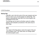
Maybe the I/O scan is asynchronous with the program scan and the latter happens before the former so I1 is 0 on that first startup scan, so use the M8 Startup flag?
Code:
    I1     M8       O1
-+--]/[----]/[---+--( )---
 |               |
 |  O1           |
 +--] [----------+
or even
Code:
    I1     M8       O1
-+--]/[--+-]/[------( )---
 |       |
 |  O1   |
 +--] [--+


xxx.png
 
Last edited:
Hello,

Thank you for your ideas and your support. Sorry for the late response, I was looking for an answer and still haven't found one. Still, I have made some progress as the more I talk to people about the issue, the more it seems to point to an hardware problem.

We recently upgraded the model of our LOGO! (from 8.2 to 8.3) so that may be a plausible cause. Two other causes are a bad expansion module (the input is on an expansion module) or a bad CPU module. I will post an update as soon as we find the root cause of this as it may help someone else.

PM
 
As a diagnostic, the value of discrete input I1 on the first scan after the PLC is started could be stored like this:

Code:
         I1       M8     I1_1st_scan
--+------] [------] [--+-----( )-------
  |                    |
  |  I1_1st_scan  M8   |
  +------] [------]/[--+
The same could be done with the value of discrete output O1.


Also, to state the obvious, I assume OP has checked if any forces are in effect.
 
Last edited:
Thank you all for your advices, you have helped me a lot. We have closed the issue when siemens support confirmed me that when LOGO v8.3 boots with an expansion module, the base module reads the expansion module's inputs at 0V since the exp. module is initializing. Issue was not present in v8.2 but now it's a fact that we have to deal with it. Hope it will help someone else !
 

Similar Topics

So you have an object on an HMI that will become a number inputted from a numeric pad, which is automatically launched on the HMI, when you touch...
Replies
12
Views
3,268
Hi all I am having a very weird problem with my control system. I have flex I/O communicating via control net to a RS5000 processor. The analog...
Replies
9
Views
5,727
Hi. OK, i have a pressure transducer for a run tank level (h20 based) that i just checked for accuracy. it's reading 3.999ma at .001in.of h20, so...
Replies
39
Views
13,862
Hello all, after finishing throwing rotten tomatoes at the screen :D please help me 🤞🏻 . I have a MOSCAD system from Motorola which...
Replies
7
Views
4,153
I am latching and unlatching "result_Data_latch" bit within same rung. Will This copy/move instruction execute correctly??
Replies
4
Views
179
Back
Top Bottom