How does the PLC get feedback?

kalimoto1

Member
Join Date
Mar 2013
Location
w dupie
Posts
20
Hi guys, I'm relatively new to the Automation field, and I hope to pursue my career in this field.

In Ladder Logic programming, we can specify the O/P Address an Output to an Input switch. If the O/P is ON, the switch will turn ON (if it's Normally Open). So IN RELAITY, how is this made possible? Is there a feedback circuit connected from the O/P to the I/P to know the status of the O/P?

And, also, I'm confused with I/P and O/P devices. Some say that Switches are I/P as well as O/P, and relays are I/P as well as O/P. Are external field devices like Motors direct O/Ps of a PLC? :unsure:
 
"???"
I believe that you may want to purse a career in management or maybe politics.


Please forgive me I have a limited understanding of the written word.
 
Last edited:
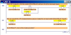
So IN REALITY, how is this made possible?
I think the situation you describe is like the attached picture. How can a PLC Output also be used in a different place as a rung Input?

The reason it can is that the PLC works with memory locations. Each memory location can have data "put in" or written, or it can have data "taken out" or read.

In the first rung 000, I used the OTE (Output Energize) to write a value to PLC memory location O:2/0.

But in the second rung 001, I used the XIC instruciton to read a value that was already in the PLC memory location O:2/0.

This method was originally an emulation of an electro-mechanical relay. The "---( )---" OTE simulates the electro-magnetic coil of a relay "O:2/0". The "---| |---" XIC instruction simulates the contact blocks for the same relay. In other words, the coil and contact are two parts of the same relay device.

You might say that the feedback circuit is built-in, because the instructions use the same memory address (which has the same value, no matter WHICH instruction addresses that value).

And, also, I'm confused with I/P and O/P devices. Some say that Switches are I/P as well as O/P, and relays are I/P as well as O/P.
Switches are hardly ever used as Outputs, but mainly as PLC Inputs. External relay contacts can be used as Inputs to a PLC. A PLC may have built-in relay outputs (literally, relays whose coils are energized by the PLC). The key is to know or find out which devices are external physical field equipment, and which are internal PLC equipment. The symbols in the PLC program ARE NOT the physical field devices, but only information that the PLC is getting from or sending to field devices.

Are external field devices like Motors direct O/Ps of a PLC?
No, external field devices such as motors are NOT normally connected directly to Outputs of a PLC. The reason is that the PLC outputs do not have the current capacity to energize 99% of the motors directly. Only a very few small toy motors can be carefully connected directly to any PLC. You must carefully check to make sure the motor cannot overload the PLC. Normally an interposing relay or motor starter would be used in between the PLC and the motor.

Kalimoto1 Output as Input.JPG
 
Last edited:
Thanks, Uptown. My interpretation of the question could be wrong, however. I find I no longer speak the same language as many younger people.
 
I find I no longer speak the same language as many younger people.
I'm also one of the guys looking for a "youngsters" language course, more especially Flemish youngsters, English youngsters and French youngsters. Anybody knows where to find :unsure: ?
 
Hi guys, I'm relatively new to the Automation field, and I hope to pursue my career in this field.

In Ladder Logic programming, we can specify the O/P Address an Output to an Input switch. If the O/P is ON, the switch will turn ON (if it's Normally Open). So IN RELAITY, how is this made possible? Is there a feedback circuit connected from the O/P to the I/P to know the status of the O/P?

And, also, I'm confused with I/P and O/P devices. Some say that Switches are I/P as well as O/P, and relays are I/P as well as O/P. Are external field devices like Motors direct O/Ps of a PLC? :unsure:

I think the mistake you're making here is in terminology. It's an easy mistake to make since ladder logic was written for people who understood electrical circuits. But make no mistake, ladder logic is NOT, I repeat NOT, an electrical circuit.

It's extremely helpful to stop thinking of the things you see on the screen as physical devices. You're using words like "switch" and "normally open" when they quite honestly don't really apply. I know that's what they LOOK like, but it's not what they actually DO.

What you're seeing on the screen are INSTRUCTIONS. A PLC processor is not a little box with a bunch of tiny relays and switches in it (at least, not for what you think). It is a circuit board with a memory chip, and what you're doing with the ladder program is manipulating data tables. That's it. That's all you're doing. You're reading and writing numbers to data tables. The PLC processor doesn't know nor care whether a certain address is an input or an output. That's all just how it's labeled for your benefit. All an address is to a PLC is a place to put a number. There are certain addresses that get manipulated by real-world inputs and outputs, but as far as the PLC is concerned, they're just numbers.

When you see a "normally open switch" in a PLC, what you're actually seeing is a read instruction. Basically ---| |--- is "Go to this address and see if a 1 is in there" to the Controller. The "Coil" you're seeing is a write instruction, so ---()--- is "If the conditions of this rung are met, write 1 to this address, otherwise write 0." That second part is important. An OTE instruction STILL DOES SOMETHING even if the rung is "false." There are other instructions like OTL which means "IF the rung conditions are met, write 1 to this address, otherwise do nothing", and OTU which means "If the rung conditions are met, write 0 to this address, otherwise do nothing."

Someone posted a link to Ron's videos. Watch them. They cover this in greater detail.
 
Yes Lancie and Donnchadh are right. and Rons videos definitely helped me I would recommend them.
 

Similar Topics

Hello i have a PV+1000 firmware ver 5.10 and a compact logix L18ERM VER 24. I googled and read many posts but still can not make simple button on...
Replies
1
Views
554
Hello parky, goghie, Brian and all of you who kindly come to help when I get stuck. I cannot look into the clock issue that parki has written for...
Replies
5
Views
853
As per the title, does anybody make a basic PLC that directly supports IO-Link without requiring a fieldbus and remote IO modules? I know it goes...
Replies
9
Views
1,655
hi to all My PLC logo (n117)does not turn on It is not clear from which part it can be? I need to fix it.
Replies
4
Views
2,197
Good afternoon all, hope everyone is doing well. Could someone explain the pic attached on the wrt.not instruction? To me, it looks the same as...
Replies
6
Views
2,107
Back
Top Bottom