Analog ~ what is your choice for a PID

What is your 'go-to' if you have the option

  • 0-10Vdc

    Votes: 3 5.7%
  • 0-20mA

    Votes: 0 0.0%
  • 4-20mA

    Votes: 49 92.5%
  • Does not matter

    Votes: 1 1.9%

  • Total voters
    53
You can measure Ohms at the field end if you can disconnect the wires. If not, then measure voltage, and assume a 250 Ohm load. If the input impedance is different, readings will be half or double what's expected.

You can only do that if you have a wire connected to the analog input common/negative in the field. If it's a two-wire loop-powered transmitter, all you have is a 24VDC from your DC P/S and the analog input positive, so you can't measure the reistance of your analog input. You can't measure voltage either - you'll get a small voltage drop across the transmitter (that is used to loop power it), but it will not correspond to the 4-20mA reading in any way.

Again, this sort of discussion is exactly the sort of discussion students should be having! Have them test a 0-10V input and see how easy it is, then have them go through the process of working out how much harder it is to do it with a 4-20mA signal in the field 🍻
 
Again, this sort of discussion is exactly the sort of discussion students should be having! Have them test a 0-10V input and see how easy it is, then have them go through the process of working out how much harder it is to do it with a 4-20mA signal in the field 🍻

This is why I always use disconnect terminal blocks for field connections on 4-20 mA loops. Set your probes, disconnect, read, reconnect, all done.
 
Built the trainer.... thank you

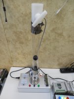
So this is what I came up with.... the scope was to build a trainer to levitate the black ball at a given height and the PID will keep the ball at the correct height, the variables are fan speed, damper at the top and at the bottom.

I figured if the PID is set up correctly it should be able to compensate for the damper position and the more or less air flow.

Its not complete yet but getting there, I know Peter and some others are fans of software driven simulators but I am a fan of hardware that I can touch and feel... also really screw up :)

What is has:
1 fan assembly that pushes the ball to the top of the tube
1 4-20 proximity switch on the top of the tube to give the PLC feedback of actual position of the ball
1 4-20 meter in showing the signal coming from the PLC to control fan speed
1 4-20 meter out going to the PLC as a feedback for position of the ball
1 manual potentiometer for fan speed control, this will be the initial setting then and the input will be the span
1 damper at the bottom of the tube
1 manual open damper switch
1 manual close damper switch
1 manual damper at the top of the tube

I hope to have the sample program (PID) wrote soon so I will upload a video

Thanks for everyone's input!

Mark

PID_Trainer_1.JPG
 

Similar Topics

  • Poll
My friend is working on a analog simulator, it may not be able to be universal voltage so what is your choice? if you were able to pick one...
Replies
0
Views
1,551
I cannot add SLC500 analog input tag (I: 8.3) to EZSeries Touch Panel Editor (V 5.3). I used all the listed tag datatype but it all says "Invalid...
Replies
3
Views
66
Hi, I have questions. I have Analog Input that need to put into Ignition Designer. But I don't know how to put?
Replies
1
Views
66
Omron AD081-V1 Analog Input Card Offset & Gain Adjustment Entering Adjustment Mode 1. Set the input card in adjustment mode (Turn ON Dip SW No-1)...
Replies
0
Views
42
Why AMIo800 Analog input module's I/O LED is Lighting up Red? Checked module connections, 4-20ma wires etc but this light is continuously Lighting...
Replies
1
Views
64
Back
Top Bottom