Asking about pwm order in plc fx1n

pmclub

Member
Join Date
Apr 2018
Location
Ho Chi Minh City
Posts
7
Hello everyone
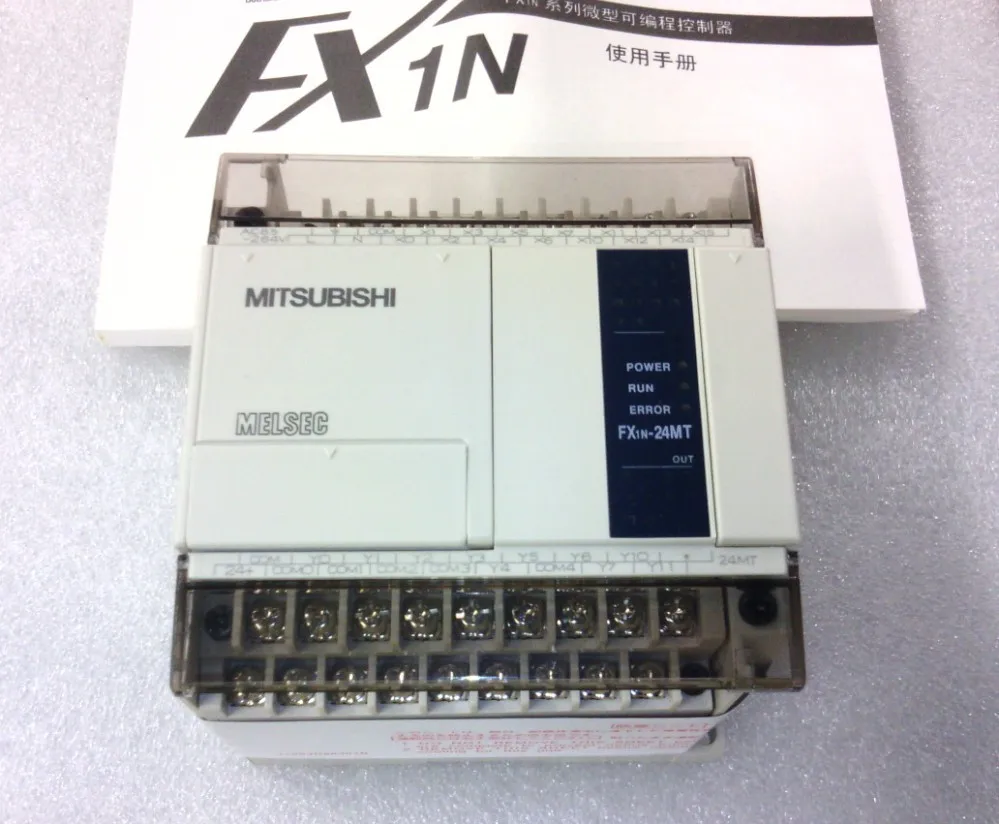
I'm using a PLC FX1n and I want to use the order PWM to create PWM pulses. I have an input voltage of 24V and I want to have an output of 0-4V. I did everything as manual but it didn't work. Can you show me how to fix it ? Thank you very much.
 
We need a little more information on your application. If the input is 24V, how is this related to the 0-4 volt output that you want?
Here are a couple of threads related to the PWM instruction in the FX1N.
http://www.plctalk.net/qanda/showthread.php?t=15628
http://forums.mrplc.com/index.php?/topic/217-pwm-on-fx1n/

Regards,
Thank you for your attention.
I want to adjust the output via the duty cycle. For example, I want the output is 4V when I choose the duty cycle is about 16%. And if I choose the duty cycle is 100%, the output will be 24V. I think PWM pulse can modify the output voltage. Can you help me ?
 
PWM means Power Width Modulation, it means the power is regulated according to the time the output is ON compared to the total period.

For example if the pulse period is 20 milliseconds and the output is 10ms ON and 10ms OFF then the power will be 50%, but a digital output has only two states OFF or ON, 0 or 24V if you are using a 24VDC power source for the ouputs.

To output a selectable variable voltage you need an analog output in your PLC
 
I read the manual and it says that I can use the PWM order to create PWM pulses with the output of Y0 and Y1. It doesn't ask us to have an additional analog module. That's what makes me confused.
 
Is yours a true Mitsubishi FX1N PLC or it's one of those China made boards ?

If it is the board probably it doesn't have the PWM implemented and therefore it is ignored.

Also for PWM to work the output has to be of the transistor type, with a relay output will never work well.
 
Yes, I'm sure that mine is a true Mitsubishi FX1N PLC. In the manual, it's very clear that this kind of PLC has the function of PWM. You can check that. And mine is a MT, so of course the output is transistor type.
 
is your PLC similar to the one in this photo ?
UT82uaNXiVXXXagOFbXa.jpg
 

Similar Topics

Happy Friday, I am trying to log scan errors related to Modbus Comms for a G306. I am able to use the system function GetDeviceStatus(x) to...
Replies
4
Views
1,919
Getting a trend of the control output, target position and actual position is a must. For a velocity control application substitute velocity for...
Replies
8
Views
2,326
Hi everyone, I would like to use Micro 850 to control DF FC 102. I adready connect Danfoss fc 102 VFD ( it can run the motor) to Micro 850 by...
Replies
3
Views
1,898
hello everyone, I have 2 PLCs controller : Micro850, and 1 HMI PV800. I use CCW to write the program. I already finished programing for both PLCs...
Replies
2
Views
1,434
I am trying to create a network setup that would take many devices that are working together and have them appear as one device or IP on a network...
Replies
3
Views
2,277
Back
Top Bottom