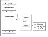
How does an PLC interrupt actually work?

sommers9

Member
Join Date
Mar 2016
Location
Here
Posts
10
(This is a rather theoretical question)

Let's say I've got a slow program with a cycle time of 200ms.

And I want to be able to set an output within 10ms after someone pressed a button.

How does the interrupt "break" the cycle?
Is it another cycle/piece that runs every 10ms?
Or is it actually something that only happens when one input becomes high?

How does the PLC know that an input has changed (since the PLC only checks inputs at the beginning of a cycle).
And will the interrupt cause my output to go high directly? (since the PLC only sets outputs at the end of a cycle?)

I'm thinking of using a Siemens S7-315 PLC, what latency can I expect (time from input signal to output signal going high).
 
Last edited:
Watch Rons great tutorial on this subject re how scanning of programs is done (AB not S) even thought it looks like you are on the money with your version on what happens.
Changing something in the PLC in 10 ms, is a bit different than something physical happening in that time?.
Regards
 
Use interrupt input card.
Something like the 6ES7 321-7BH01
Enabled Hardware interrupt.
Select which inputs need to trigger interrupt. Pos and/or Neg flank.
In Blocks folder, add OB40.
This OB will be called when the input triggers the hardware interrupt. All logic in OB40 will be executed only once.

If you have a single input calling the interrupt, then it's easy.
If you have multiple inputs calling an interrupt, then you'll have to use the temp data "OB40_POINT_ADDR" and "OB40_MDL_ADDR" to find out which input called the interrupt, so you can run the appropriate code.

Setting outputs before the end of the scancycle is done by addressing them as peripheral outputs.
Code:
L QB 2 
T PQB 2
This way, you force the update of the outputs.
Take care: This will force an update of at least 8 outputs. This can be potentially dangerous because OB40 will be called the moment the interrupt is triggered. Normal scancycle will be interrupted, regardless of what it is doing atm and then continued once OB40 has been executed.

It is entirely possible to have a Set/Reset piece of code for an output, where you Set the output and Reset it in the same scancycle (bad practice I know, but it happens).
In this case, if OB40 is called just after the Set and before the Reset, and said output is part of the (minimum) 8 bits you are updating in OB40, it WILL be activated. Until the end of the scancycle.
In a 200ms scancycle, this can mean an unintentional activation of an output for up to ~190 ms.

To prevent this, we make a copy of the output states at the end of the scancycle and use that as a template should we need to force an update mid-cycle in the next scan.
Only change the bit(s) that needs updating, then T PQB x and done.
 
@Duckman
Hmm, good point on checking out some tutorials, I'll check the basics first and then try to find an tutorial about "perhiperal" interrupts.

@Jeebs
Thanks, that's a rather complete and practical example.

I've attached an image of the situation I'm trying to create.

The situation I'm trying to create is the following:

1. PLC receives a message from the server (over TCP/IP). The message tells it to send a character 'S' to a peripheral device (which does not have profinet/profibus but an "SPI" connection).

2. The main program loop will stop (or interrupt) to start a shorter, faster loop that is able to set outputs very fast. (And really output them, not just setting, but actually applying voltage :) )

3. One clock-output will be toggled while the data-output indicates a 1 or 0 on this edge. (These have to be synchronous)

4. The complete 'S' has been sent to the peripheral device, and we continue with the main/slow loop.

Is there any way to create this kind of behaviour?

PLCpossibility.jpg
 
You need normal program and fast programs on PLC (you get data from TCP/IP, so you need only fast program for looking data change and setting output)

On Siemens we are talking some fast OB-clocks (OB35-OB37 maybe depending of how fast you need response) and normal OB1 for everything else)

On fast OB-block look data message and then set directly output(s) with PQB/W addresses (peripherial).
If you use normal Q-outputs on fast OB, they are only setted when normal OB1 cycle is ended.

You maybe need to use peripherial address for TCP/IP on OB3x so you get data also between OB1 scans?
 
Last edited:

Similar Topics

Hello i have a PV+1000 firmware ver 5.10 and a compact logix L18ERM VER 24. I googled and read many posts but still can not make simple button on...
Replies
1
Views
554
Hello parky, goghie, Brian and all of you who kindly come to help when I get stuck. I cannot look into the clock issue that parki has written for...
Replies
5
Views
851
As per the title, does anybody make a basic PLC that directly supports IO-Link without requiring a fieldbus and remote IO modules? I know it goes...
Replies
9
Views
1,655
hi to all My PLC logo (n117)does not turn on It is not clear from which part it can be? I need to fix it.
Replies
4
Views
2,197
Good afternoon all, hope everyone is doing well. Could someone explain the pic attached on the wrt.not instruction? To me, it looks the same as...
Replies
6
Views
2,107
Back
Top Bottom