ivo.maenen
Member
- Join Date
- Nov 2003
- Posts
- 663

I have received some used Asi-bus material. All the material was used in a plant and in good working condition.
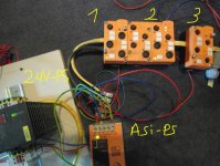
At his moment I'm just testing the hardware. So my test-setup is without a asi-busmaster.
The system uses a asi-bus-powersupply for the yellow cable and a normal 24Vdc-PS is used for the black powercable.
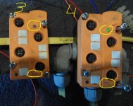
The strange thing is that module 2 and 4 have power, but the module 1 and 3 not. Module 4 is at the end of the yellow cable, so the last module.
The powerled-problem is only with the IFM AC2500-modules.
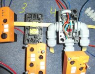
I have tested all AC2500-modules on the screw-base that is used for position '4'. And all AC2500-modules their powerleds are green when used with this screw base.
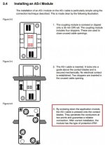
But with the non-screw bases the powerled is always off. I think that the base of module '1' is adressable and the base of module '3' is not adressabel. Please correct me if I'm wrong.
My question is:
why does the powerled of the AC2500-modules stay off when used with the non-screw bases?
Regards,
Ivo


Last edited:


