[email protected]
Member
Hello,
I have a simple PLC program I hope someone can help me with. I have created my own ladder program and would simply like to make a comparision with someone elses
the following is the program:


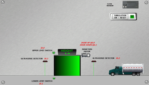
THIS SIMULATION IS OF A DOOR APPROACHING AN ULTRA SONIC DETECTOR. THIS DETECTOR PUT THE DOOR MOTOR INTO FORWARD DIRECTION IN ORDER FOR THE DOOR TO BEGIN TO OPEN. WHEN THE DOOR REACHES THE UPPER LIMIT ON THE DOOR THE MOTOR MUST STOP. THE TRUCK WILL THEN CONTINUE ON ITS WAY THROUGH THE OPENING. THE DOOR WILL AUTOMATICALLY CLOSE ONCE THE BACK OF THE TRUCK FINISHES PASSING THE SECOND ULTRA SONIC DETECTOR. THE DOOR CLOSES BY PUTTING THE MOTOT IN REVERSE AND CONTINUES UNTIL IT REACHES THE LOWER LIMIT. CLICK ON THE PICTURE TO SEE A SIMULATION OF THE FINISHED WORKING PROGRAM.
there are alos three errors that must be avoided
ERROR 1
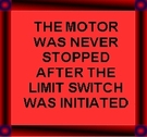
 YOU WILL GET THE FOLLOWING ERROR IF YOU FAIL TO STOP THE MOTOR AFTER YOU REACHED THE UPPER LIMIT SWITCH
ERROR 2
 YOU WILL GET THE FOLLOWING ERROR IF YOU PUT THE MOTOR IN FORWARD AND REVERSE AT THE SAME TIME.
ERROR 3
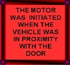
 YOU WILL GET THE FOLLOWING ERROR IF YOU START THE MOTOR IN REVERSE BEFORE THE TRUCK HAS CLEARED THE DOOR AREA
I.E. THE BACK OF THE TRUCK MUST FINISH PASSING THE SECOND ULTRASONIC DETECTOR BEFORE YOU CAN ATTEMPT TO CLOSE THE DOOR.
thanks
I have a simple PLC program I hope someone can help me with. I have created my own ladder program and would simply like to make a comparision with someone elses
the following is the program:


THIS SIMULATION IS OF A DOOR APPROACHING AN ULTRA SONIC DETECTOR. THIS DETECTOR PUT THE DOOR MOTOR INTO FORWARD DIRECTION IN ORDER FOR THE DOOR TO BEGIN TO OPEN. WHEN THE DOOR REACHES THE UPPER LIMIT ON THE DOOR THE MOTOR MUST STOP. THE TRUCK WILL THEN CONTINUE ON ITS WAY THROUGH THE OPENING. THE DOOR WILL AUTOMATICALLY CLOSE ONCE THE BACK OF THE TRUCK FINISHES PASSING THE SECOND ULTRA SONIC DETECTOR. THE DOOR CLOSES BY PUTTING THE MOTOT IN REVERSE AND CONTINUES UNTIL IT REACHES THE LOWER LIMIT. CLICK ON THE PICTURE TO SEE A SIMULATION OF THE FINISHED WORKING PROGRAM.
there are alos three errors that must be avoided
ERROR 1
 YOU WILL GET THE FOLLOWING ERROR IF YOU FAIL TO STOP THE MOTOR AFTER YOU REACHED THE UPPER LIMIT SWITCH
ERROR 2
 YOU WILL GET THE FOLLOWING ERROR IF YOU PUT THE MOTOR IN FORWARD AND REVERSE AT THE SAME TIME.
ERROR 3
 YOU WILL GET THE FOLLOWING ERROR IF YOU START THE MOTOR IN REVERSE BEFORE THE TRUCK HAS CLEARED THE DOOR AREA
I.E. THE BACK OF THE TRUCK MUST FINISH PASSING THE SECOND ULTRASONIC DETECTOR BEFORE YOU CAN ATTEMPT TO CLOSE THE DOOR.
thanks


