Dh 485 msg

Stevezav

Member
Join Date
Sep 2020
Location
Indiana
Posts
4
I have a micrologic 1000 that has a msg read and msg write to an slc that is supposed to be node 1. After troubleshooting intermittent comm issues I discovered The SLC was actually node 7 on its ch1 dh485. How on earth did this work ?
 
Is channel 1 being used for this communication? Most SLC's have 2 channels. Are you sure the other channel is not being used for this?

Post both programs if you can. Zip them first. Someone can take a look. (ditto geniusintraining)
 
zipped prog

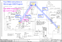
12065 la contains msg to 1 slc at node 1 and another slc at node 5

They both work but the node 1 has intermittent issues . the 2 slcs are actually node 7 and node 5
 
Steve, welcome to the PLC Talk forum community. You've brought diagrams and program files to your first thread, which is awesome.

My first take is that the program file you have that shows the SLC-5/03 as DH485 Node 7 must be incorrect, and that the controller is actually at Node 1.

That would explain why the MSG in the MicroLogix works at all, and it would be consistent with the network diagram.

The way to figure it out would be to get online with the DH485 network, through the 1747-KE or a 1747-UIC, and browse the network nodes.

I have a guess (I have to run to a meeting and won't be able to explain in detail) that the T4:32 and T:33 timers in the MicroLogix LAD8 file, and the way they are used to trigger and interlock the MSG instructions, are why the Node 1 message seldom works.

The way I read it, unless the MSG on Rung 16 completes in under 20 milliseconds, its /EN bit will prevent the timer from triggering the MSG on Rung 14.

There are other ways to write timed MSG triggers... more on that later.
 
I will bow out and let Ken answer... one thing I would like to add is I dont see 5d I see 1 writes/reads to 4 and 7

I worked on a DH+ system once that they had some writes and the nodes on the other end you had no idea where it was coming from but at least it looks like you have good documentation, is it possible that someone changed 5 to 7?
 
The only thing that makes sense is that the SLC-5/03 program that was Zipped and attached, which is clearly set as DH485 Node 7, is actually installed as DH485 Node 1.

The only reference I see to Node 7 is in the zipped SLC-5/03 program. It's not addressed by any of the MSG instructions I saw in the MicroLogix program.

An examination of the actual network, and/or the other SLC-5/04 program, and/or the PanelView Plus configuration, might help settle that. The most helpful thing would be a browse of the actual network.

There is no realistic possibility that the MSG instructions from the MicroLogix (Node 4) to DH485 Node 1 are working, ever, if that SLC-5/03 is actually configured and running as Node 7.

By "no realistic possibility", I mean that in a billion years the correct coincidence of checksum and data corruption will eventually occur. But not often enough to be "intermittent" in the scale of human lifetimes.

MSG Block Diagram.png
 
Last edited:

Similar Topics

Dear Messes, I am working on 2nos. SLC5/05 plc and I had set those Channel 0 & 1 as Passthru, i.e.: the RS232 as DH485 with Net-AIC at...
Replies
1
Views
2,647
Hello all: A while ago, my partner Sean and I (college students) had posted on the forums for help setting up our DH-485 network. We are trying...
Replies
5
Views
2,336
I have been working with InView P42C Message Displays communicating with SLC 5/05 through 1761-Net-AIC RS485 multidrop. I have 46 messages and 59...
Replies
2
Views
2,769
I'm trying to control a device via MODBUS RTU and the ModbusRtuMasterV2_PcCOM in Twincat 3. I've configured a device with the right com port and...
Replies
6
Views
134
I'm trying to write a data in Arduino using MODWR function block .I used the code I got from online for both PLC and Arduino. I made the wiring...
Replies
4
Views
90
Back
Top Bottom