Hi all,
Using a 1734-VHSC for the first time (the 24V version). I think I have the theory of how to make it do what I want down, but it would appear that sometime in the last 12 years AB updated the input data table for the module, and didn't think it necessary to update the manuals. The last manual I've been able to find for any 1734 counter module is August 2005.
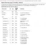
For the sake of making sure I have all my t's crossed and lower case j's dotted, can anyone point me to any updated documentation that explains the input data structure? Alternatively, can you help me confirm my suspicions and fill in the blanks below?
Fault (DINT): presumably either a fault code, or a word containing 32 bits that represent 32 different faults. Does a list of these faults/fault codes exist somewhere?
PresentData (DINT): Current counter value
StoredData (DINT): Stored counter value from when the configured "store" operation was last enacted
Status (INT): presumably contains a status code of the module. Does a list of these statuses (stati??) exist somewhere?
ZeroFreqDetect (BOOL): detects zero counter frequency, when configured
StoredDataCount_2, StoredDataCount_3 (BOOL): Two-bit binary value which increments to confirm that the store operation has been enacted
AInputStatus, BInputStatus, ZInputStatus (BOOL): Status of inputs A, B and Z
OutputStatus_8, OutputStatus_9 (BOOL): Status of outputs 1 and 2 respectively
OutputFault_10, OutputFault_11 (BOOL): Fault on outputs 1 and 2 respectively (based on what IS in the manual, probably a hardware fault, rather than a configuration fault)
NotReady (BOOL): Module is being initialised
EEPROM Fault (BOOL): Fault with EEPROM unit in module
ProgramFault (BOOL): Configuration problem with the module (?)
Thanks everyone!


