Omron CP1E and Modbus RS485

Raptorex

Member
Join Date
Jun 2018
Location
Ontario
Posts
8
Hey Folks,

I have a question regarding how the CP1E stores its received RS485 data.
Please be easy on my explanation lol, detailed rs485, HEX info and data registers are new to me.

A quick overview of the project, im working on a personal project and experimenting with RS485 communication so I can slowly get comfortable with it, and begin learning how to integrate it into future projects.
Im designing a Generator switchover system using a Omron CP1E-N30DR-D and have a addon CP1W-CIF12 rs485 card, its the same as the CIF11 just with opto isolation. The unit will also have a NB7W HMI that I will remote mount and use it to control and show parameter data, and connect it to the spare fixed RS232 port on the plc.

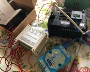
With that I have a simple 4ch current and voltage module that can sense current on 4 feeds, and voltage on 4 feeds, and sends the data over the RS485 line once it is asked by the PLC.

I learned and slowly figured out how to get the module and PLC to talk, and now I have continuous data flowing between the 2, I wrote a simple program that writes the required bits to the D1300 to D1305 memory registers, and sends it away to the power module. The PLC sends the read register command ( 01 03 00 00 00 28 45 D4).

In response the Power Module sends back ( 01 03 50 02 74 00 78 01 C2 00 01 18 04 00 00 00 03 06 00 00 00 00 00 00 00 00 00 0B B8 03 E8 00 00 00 00 00 00 00 00 00 00 00 00 0B B8 03 E8 00 00 00 00 00 00 00 00 00 00 00 00 0B B8 03 E8 00 00 00 00 00 00 00 00 00 00 00 00 0B B8 03 E8 00 00 00 00 01 D6 00)

Which is fine, I have the data sheet that describes what the HEX bits are, and im working on how to convert them to useable decimal values.

Im using a RS485 to usb adaptor mid line to view the send and receive data between the 2.

Now here's my problem.

This data gets dumped into the data registers D1350 to D1399, but there doesn't look to be enough space to store it all. D1400 and on, has a bunch of other random data. Is there anything I can do to utlize all the data being sent back. Although I only need 4ch of Amps, and 4ch of Volts, there are also many other channels of data such as Hz, Watts, and PFC.

Any help would be greatly appreciated :p
 
Last edited:
It appears you are using the 'Modbus-RTU Easy Master' function in the CP1E? I haven't used the CP1E but many of the CP1L & CP1H in which I believe the Modbus functions similarly.


I can't quite parse your 'read register command' but you should be able to shorten the length of your read area in the slave and then set up your program to do multiple Modbus commands on the different data areas you need from the slave.
 
but you should be able to shorten the length of your read area in the slave and then set up your program to do multiple Modbus commands on the different data areas you need from the slave.

I can experiment with that. First I will try seeing if the power module will respond to only sending a selection of data, instead of all the data when asked.

There is almost no support with the power module, so anything not in its basic manual is an experiment. I will try it out with the USB interface and the serial monitor in windows and see if I can get the power module to send 1/2 the data at a time.
 
I just used http://modbus.rapidscada.net to decode your request and it says that you are requesting 40 registers starting from register #1.

So the D1350 to D1399 seems more than an adequate size for the number of registers you are requesting (99-50=49)

Your response has an extra 00 at the end. Deleting that and plugging the rest into the decoder shows that 80 bytes (40 registers) was successfully returned.

But what is the power module that you are referring to? I can't figure that out from your post. And that will tell me what you can read from that device
 
If that doesnt pan out, I have rolled my own Modbus Master in the past on the CP1 series PLCs using standard TXD / RXD instructions. Then you can set a much longer response area. The catch is calculating the CRC but I have a Function Block somewhere for that. I believe I found it over at MrPLC.com
 
I just used http://modbus.rapidscada.net to decode your request and it says that you are requesting 40 registers starting from register #1.

So the D1350 to D1399 seems more than an adequate size for the number of registers you are requesting (99-50=49)

Your response has an extra 00 at the end. Deleting that and plugging the rest into the decoder shows that 80 bytes (40 registers) was successfully returned.

But what is the power module that you are referring to? I can't figure that out from your post. And that will tell me what you can read from that device

Yes I see what your saying. I should have enough space to fit all the data

The response from the power module above is what ive observed is sent to the plc via my 485/usb monitor.

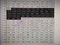
Now ive attached a pic of what the actual registers read in the plc, and it seems like they are getting bumped down with a lot of filler 00 at the beginning few lines. Now this data only shows up in the register monitor when I stop the communication.. While the communication is running, all it shows is 0000 im assuming is because it doesn't refresh thru CX-programmer quick enough.

My USB RS485 terminal on the pc is constantly showing the data going between the 2.

attachment.php


attachment.php


Now the power module.. here is a link to the product, its honestly the only thing I could find that had enough channels that actually existed, without going into a commercial product for this type of experiment.
The manual is definitely not in English lol, but Google translate has helped greatly.

The unit I have is the 120A model.

https://www.aliexpress.com/item/4-w...easurement-sensor-module-485/32828004243.html

Here is the company website, translated into English for everyone's use
https://translate.google.ca/transla...8&u=http://www.huidkj.com/&edit-text=&act=url

And here is the product manual translated:
https://translate.googleusercontent...700201&usg=ALkJrhjtA3x9xhSPERL2SKqSqH-hhylZ_A


After looking at the data.. For example "01 03 50 02 74 00 78 01 C2 00 01 18 04 "

02 74 in HEX = 628 DEC which corresponds to 0000H for version 6.2.8
00 78 in HEX = 120 DEC which corresponds to 0001H for 120A version
01 C2 in HEX = 450 DEC which corresponds to 0002H for 450v version (im only using this up to 120v for my experiment

Later on you can see the variable that actually change once current and voltage is applied.


The PLC however is storing extra 00 in between the address for the first few group of numbers.. Its slowly sinking in with me, please be patient lol
As of this morning, I didn't even have any communication, so im slowly moving forward.

It looks like the useful data starts half way thru register D1354 at 02, then D1355 (74 00)..... and on


Thanks.

IMG_2203.jpg IMG_2204.jpg
 
Last edited:
The PLC however is storing extra 00 in between the address for the first few group of numbers.. Its slowly sinking in with me, please be patient lol
I think that a key thing you may be missing is that Modbus is a Register based protocol and not a Byte based one. So data that is always returned as 16 bit Registers and not individual 8 bit bytes. Hence all the 00's you are seeing are the upper byte of the register being zero. Decoding some of the data from that manual gets you:

Code:
02 74  = register 0 => Version 6.2.8
00 78  = register 1 => Current Range (120A)
01 C2  = register 2 => Voltage Range (450V)
00 01  = register 3 => Comms setting (9600, 8, N, 1)
18 04  = register 4 => Factory Date (April, 2018)
00 00  = register 5 => Current Rate (something default)
00 03  = register 6 => Sampling Interval (3 Cycles)
06 00  = register 7 => (High Byte) Signal result threshold (Low byte reserved)
00 00  = register 8 => Chan A Current [x .01A]
00 00  = register 9 => Chan A voltage [x .01V]
00 00  = register 10 => Chan A apparent power [VA]
00 00  = register 11 => Chan A active power [W]
0B B8  = register 12 => Chan A current transformer ratio
03 E8  = register 13 => Chan A voltage transformer ratio
00 00  = register 14 => Reserved
00 00  = register 15 => Reserved

etc

But what is more useful is registers 40 to 55. These concatenate the active data parts of the memory map into one contiguous block of 16 registers. This allows you to get the most active data by reading the least amount of registers. As after all it is a waste of data to continually read the version number and factory date of the product.

Ah ha I see now! (y)

Yes. Ok.. so I should just try and read registers 40 to 55 now. It seems to have all the data I would need. I was wondering why they seemed to repeat the same info twice.

So with that said, instead of using the command to read the first batch of registers (01 03 00 00 00 28 45 D4).. would something like (01 03 00 28 00 0F C6 85 ) work to read the 40 - 55 registers only?

I used https://www.lammertbies.nl/comm/info/crc-calculation.html to make the CRC - C685 ...

or am I way out in the field?. lol


Looks like after testing (01 03 00 28 00 0F 85 C6 ) it seems to work!.. odd that the CRC is backwards.
 
Last edited:
So with that said, instead of using the command to read the first batch of registers (01 03 00 00 00 28 45 D4).. would something like (01 03 00 28 00 0F C6 85 ) work to read the 40 - 55 registers only?

I used https://www.lammertbies.nl/comm/info/crc-calculation.html to make the CRC - C685

or am I way out in the field?. lol

From that link I previously mentioned you have the byte order of the CRC the wrong way around. When I changed that I get (excuse the formatting)

Code:
Part of Data Package	Description	Value
01    Slave address          0x01 (1)
03    Function code          0x03 (3) - Read Holding Registers
00 29 Starting address       0x0029 (41)
00 0F Quantity	             0x000F (15)
85 C6 CRC	             0x85C6 (34246)

It looks like you are out by one for the number of registers to read. And I am never sure if the starting address should be in the data as 41 or 40.

But basically that's it.

Awesome! I just did a quick test, and it looks to be sending the new batch of data. Ill have to take a break tonight. But I just quickly hooked up my variac to voltage channel A, and I do get readings! 2CBA = 11450 = 114.50V (y)

Ill take a look at the memory registers tomorrow in the PLC and go from there.

Thanks :)
 
I thought I would give it one more try before the day is over.

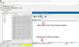
Ok, so attached is a screen shot of the serial monitor, and as a confirmation from before. (01 03 00 28 00 0F 85 C6) does start at the 40th register which would be in this example 0028H - Channel A current. And I was able to confirm that by placing the current clamp on a load, and I got a reading (00 9A) = DEC 154 = 1.54A.. so the module works.

So here is where im confused.

It looks like, in the PLC, the registers are shifted by 1 value.

Heres what I mean, ive attached a photo.

I know that in the below data stream (01 03 0D 0A 1E 00 9A 00 00 00 .....) 00 9A relates to the first read register #40.. however in the plc

The first value of the HEX register, ends up being in the register before.
the 0 from 00 9A, is ending in the D1354, and D1355 ends in a 0 from the next register.

Am I just over thinking it?

I know that isn't the best example, because 00 9A starts with a 0, but it does the same thing for example if it was a 2B 75, the 2 would be ending in D1354, and D1355 would be (B75x) the x being the first value of the next register.

Once I understand this, and can move the individual HEX registers in the plc, I can then convert to Dec, and do math so I can play with the values to show on the display, and enable logic.


Ultimately imo for example I would want:

D1355 to be - CH A current
D1356 to be - CH B current
D1357 to be - CH C current
D1358 to be - CH D current
D1359 to be - CH A Voltage
.....

attachment.php


plc reading.jpg
 
Last edited:
The PLC needs to be addressed to the direct number not the Modbus number - hence do not address 40001 for exmple address 40000 - 1 to the left. This is quite normal.
 
The PLC needs to be addressed to the direct number not the Modbus number - hence do not address 40001 for exmple address 40000 - 1 to the left. This is quite normal.

I slightly understand what your talking about. But im still very green in regards to what your explaining above. I do remember reading something similar to what you said throughout my searches online. But couldn't find an explanation that made full sense to me.

Or in simpler terms for me to understand. For example, I want to take a register value and move/copy it into another memory location once every second so I can then use that new memory register to do my math, calculations, and screen data source. How would I go about doing that? Or are we talking about something completely different? :confused:


Or completely scrap that ideal, is there a simple way I can shift the registers by +1 between cycles, or read the registers with a -1 offset to I can grab the correct 4 character hex data, move/copy it to a different memory location and do my calculations from it?


Ive taken both the beginner and intermediate Omron supplied PLC courses, but we never ended up getting into register/memory manipulation, so that's why im still very green on the subject, and ive always been a learner by doing or seeing examples.
 
Last edited:
No need - read word 0 not word 1 - Omron reads the real address (direct) not the Modbus address - the real address would be 40 for example and the Modbus address 41 - an offset of one. Working with Schneider at the moment and for my comms I have set up to read the real address and not the Modbus address - working well.
 
The PLC needs to be addressed to the direct number not the Modbus number - hence do not address 40001 for exmple address 40000 - 1 to the left. This is quite normal.

Its called zero offset addressing. One platforms address base value is zero, the other platforms address base value is one. And as you mention its very common to have to poll a zero offset to get the desired value (ie poll reg 49 to get the data from the targets reg 50). Sometimes you'll even see the holding register stripped of the leading 4 bits and any zeros, leaving you to poll address 49 when you want to get data from 40050.
 

Similar Topics

Hello! I have tried to communicate with a Danfoss drive Aqua FC301 over RS485 but I had no sucess! Attached you will find the demo project that...
Replies
7
Views
4,280
Hello. I have a problem with omron sysmac cp1e controller delayed start. The controller has been working on the punch press since 2016. Recently...
Replies
1
Views
755
Hi, I need to communicate omron CP1E PLC with SCADA to get the status of the machine. There is no etherent port available but an empty expansion...
Replies
2
Views
1,593
Hello... I remove one CP1E from old useless machine and I would like to use it with something else....but it is locked/have no pass/....How can I...
Replies
0
Views
1,436
hi all i have used a real time clock to turn on a bit after 1 month. the plc was off for this whole month and when i turned on the plc after a...
Replies
2
Views
1,414
Back
Top Bottom