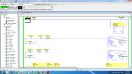
PowerFlex 525 -- SLC 5/05 -- EEM Instruction

PowerFlex N-table emulation makes the infant Jesus cry.

There are three methods for controlling the speed of a PowerFlex 525 or other A-B drive over Ethernet from a MicroLogix 1100/1400 or SLC-5/05.

1. Use a CIP Generic message (or EEM, in the SLC-5/05) to write to the CIP Output Assembly Object repeatedly, to functionally simulate a cyclic I/O connection.

2. Use a PCCC message (MSG instruction in MicroLogix or SLC) to write to the emulated N41 Data Table addresses for Command and Reference and Timeout values.

3. Use one of the above messaging methods to write to the Parameter Object (with an EEM) or to the emulated SLC-500 Data Tables that represent Parameters (with an MSG) to write to a Preset Speed variable. Care should be taken to write to these values infrequently, or to use the function code or option parameter to be sure that these do not result in a nonvolatile memory write.


The logic shown by our colleague Padees is an example of the second method.

I do not recall if you can write to just N41:2 (the Reference value) and not to N41:0 (the Command value). I don't think that you can; you should find that the PowerFlex rejects such a message. Write to N41:0, Length 3, to cover the Command register, the unused register, and the Reference register.

The unused register is in there to make it similar to PowerFlex 700/750 series, which use a 32-bit Reference. PowerFlex 525 is a 16-bit reference value.

In the example that Padees showed, you can see that he is using the Command register to perform a Fault Reset on the PowerFlex. (bit 02 of the Command register).

The Start and Stop bits in the Command register have no effect when set to zero, so there's no harm in sending a zero to the N41:0 and N41:1 words in the same payload as you are sending the Reference to N41:2. I would recommend writing a constant zero to those registers in logic immediately before the MSG instruction.


Because method #2 emulates a cyclic I/O connection, you must also write a nonzero value to N42:3 for a Timeout value, and then keep writing to N41:0-2 more frequently than that number of seconds.
 
Never heard about the non-volatile failure thing. Kinda scary. I coded mine to write all values every 250ms via a message regardless of if they changed. I haven't gotten a call back yet :confused:


Yeah, and I use automatic message triggers. What was I thinking!:sick: Ha!
 
Last edited:
Thanks Ken, I'm most interested in trying to implement method #1 as you have pointed out. However, I simply have been unable to find the structure (or perhaps individual parameter #) of the CIP Output Assembly Object. I've seen sample code in one of the Rockwell Knowledgebase articles showing exactly how to do this to write to P041 (Accel Time 1). My basic trouble is I can't find a simple parameter that I would think of as "Commanded Frequency" to write to. Am I just overlooking it or is my way of thinking incorrect?
 
Pee Triple Cee

If you insist on doing this at all, method #2 is the most straightforward, best documented, and most supportable.

I recommend against using the Assembly Object or the Register Object to control a PowerFlex VFD with messaging from an SLC-5/05. The details about the Class, Instance, and Attributes, including the Timeout attribute, are available in the 520COM-UM001 user manual in Appendix C. But they're really there just for reference.

The CIP Assembly Object is not controlled or accessed by the Parameter Object. There is no equivalent "Parameter Number" you can write to that will be used when you have selected P047 = 15 for EtherNet/IP Reference.

However, the "PCCC Object" emulates SLC-500 Data Tables, and provides an easy and well documented "side door" to the Assembly Object. This is what's documented in various examples and in the 520COM-UM001 user manual Appendix C under "PCCC Object".
 
Also: I see that you're relatively new to the PLCTalk forum community, so I don't want to be a curmudgeon.

But this specific issue has been a sore spot for me for years. I've spent countless hours explaining the details of everything that can go wrong with this method.

And for some reason, this topic is one where folks seem to stomp the accelerator and drive into a ditch, and then complain that I was not clear enough in explaining the importance of the road.

You should be able to find examples of writing to N41:0, Length 3, to send the Command and Reference values. Leave the Command word at all zeroes.

If the message errors out with an "illegal command" error, that indicates that the drive has been power cycled since the last time you wrote a value to N42:3 so you need to re-write to the Timeout.
 
I completely understand Ken and I appreciate your input. I have read several of your other posts so I was prepared for some "tough love". This issue, like many others is an imperfect fix to an even worse system. This machine is an old paint line. The VFDs being added replace ancient DC Drives. If I could swap the processor for a Logix I would. If I could do analog speed control instead of networked, I would. Sometimes imperfect solutions are all that's left.

Incidentally, I've read through Appendix C of the Comms manual and I came across (seemingly) the exact parameter I wanted access to. It's 2001H but it's only listed in the RS-485 (DSI) Protocol section, nothing for E/IP. So strange that there isn't an equivalent.
 
Great research !

Even though it's "embedded", the PowerFlex 525's Ethernet port is still basically an EtherNet/IP to DSI adapter like the 22-COMM-E.

Any DSI device that's connected to the drive is going to write to the internal "Comm Frequency Command" register, which is available via Modbus as Register 0x2001 (hex).

And you can write to that over Modbus and the DSI port, if you had that sort of interface.

Of all the things that can write to that register; the EtherNet/IP Adapter via the Assembly Object, and via the Register Object, and via the PCCC Object.... the one that is excluded is the Parameter Object.

This is because it's just not a Parameter. It isn't stored in the nonvolatile memory with other Parameters, and it's not part of the Configuration features that store or compare Parameters.


"Imperfect Solutions" would be a great name for an automation integration company.
 
...and now I will show my immense ignorance. I was with you until your conclusion statement.

Even though it's "embedded", the PowerFlex 525's Ethernet port is still basically an EtherNet/IP to DSI adapter like the 22-COMM-E.

Any DSI device that's connected to the drive is going to write to the internal "Comm Frequency Command" register, which is available via Modbus as Register 0x2001 (hex).

And you can write to that over Modbus and the DSI port, if you had that sort of interface.

So it's possible.

Of all the things that can write to that register; the EtherNet/IP Adapter via the Assembly Object, and via the Register Object, and via the PCCC Object.... the one that is excluded is the Parameter Object.

This is because it's just not a Parameter. It isn't stored in the nonvolatile memory with other Parameters, and it's not part of the Configuration features that store or compare Parameters.

So it's not possible.

Forgive me, I've lost the plot.
 
Last edited:
Edit:
Just to be more clear, the issue is my limited understanding of what constitutes an Assembly Object vs Register Object vs Parameter Object vs Modbus Register. I'll need to read up on that before I ask any more questions.
 
So I'm now in the midst of bench testing and I've discovered a few things.

I can use the EEM instruction to read the speed reference. That's good.

As expected, I cannot use the EEM instruction to write to a speed reference parameter because as Ken explained, it's not that simple.

I have successfully used a MSG instruction to send a Timeout value to the drive (destination N42:3).

However, I'm now trying to send the 3 word MSG to the drive so that I can control the speed reference and I'm running into an issue. The MSG error code is f0 "No Access". I've set P047, P049, and P051 to '15' just to be sure the drive is expecting a networked speed reference, still no luck. Not sure what "No Access" means but I'm assuming a parameter hasn't been correctly set somewhere. Any pointers would be greatly appreciated.
 
rupej, I have no doubt it is possible. After abandoning my original idea of using the EEM instruction and going with the more typical MSG solution as padees and Ken have mentioned I was hoping to be out of the woods. Something, probably silly that I've overlooked is getting in the way.
 
I think what you are seeing is the action of the Timeout/Watchdog feature.

To do this sort of control, you need to start by writing a nonzero value to the Timeout register (N42:3). I read a technote that suggested values between 5 and 20 (seconds).

Between power-up and when the Timeout has been set to a nonzero value, the Ethernet port will reject MSG Writes to the Command/Reference registers (N41:0,1,2). That's why you see the 0xF0 error code.

After the drive has received that nonzero value, it will accept MSG writes to the Command/Reference registers.

But if no messages are received in X number of Seconds, the Timeout will take the selected action (usually to stop the drive) and the Ethernet port will go back to rejecting MSG Writes to N41:0,1,2.
 
Ken, it seems I'm able to send the Timeout value successfully. Upon successful completion of that I then immediately send the 3 word MSG and that's when I get the "No Access" error. It's true that I'm only sending the 3 word packet once but my plan was to make it happen repeatedly once I prove that my code works. Anyhow, the 3 word MSG displays an error immediately upon execution, well within the Timeout value that I set immediately prior. I'll try to attach a pic of my test code for clarity.

MSG.png
 
Last edited:

Similar Topics

I'm having a strange issue where the operator can input a desired speed in 0-110%, and the scaling will correctly translate that in Hertz to the...
Replies
6
Views
2,265
I have decided that instead of upgrading the drives & plc at the same time on my project i would just do the drives for now as just getting them...
Replies
23
Views
8,946
Going back to a 15 year-old project and upgrading the drives to PowerFlex 525. SLC 5/05 was controlling three non-AB drives with analog (for...
Replies
6
Views
9,428
Hi to all. We need to change a bad powerFlex 525 to a new one. How do you save the configuration to install in the new one? Thank you all for...
Replies
5
Views
222
Im trying to teach a couple of labs on VFDs at a community college. We have some motor control trainers with P525s and 3 phase motors from...
Replies
2
Views
227
Back
Top Bottom