The first scan bit, S2:1/15 in RsLogix 500

freeali

Member
Join Date
Apr 2015
Location
somewhere
Posts
23
Dear Sir,

Can you please tell me how to use the first scan bit, S2:1/15 in RsLogix 500 to Prevents the latch output to be ON when the power cutoff on the PLC ?

I mean if I make a latch to the Output#01 and during the working the power is OFF on the PLC then when the power back to the PLC this output will be ON directly because of the latch instruction. I don not want that to happens, I read on the internet that we can use the First scan bit S2:1/15 to stop that but I do not know how to do that , please help me. Thanks

Latch.jpg
 
Try putting a branch around your red button and in the branch put a NO S2:1/15, then when the PLC is powered up for the first time it will make O:0/1 true for the first scan
 
Expanding on what GIT wrote, I think this is what you are looking for.

Code:
      Green             O:0/1
 -------] [---------------(L)---


       Red              O:0/1
---+---] [---+-----------(U)---
   |         |
   |  S:1/15 |
   +---] [---+
You may want to think of the First Pass bit as a virtual "button," like your Red button, but one that that is automatically "pressed by the PLC" itself during, and only for, the specific case of a "First Pass" scan.


From reading your post, I assume that your intent is that you want to Unlatch O:0:1 either

  • when the Red button is pressed
  • OR
  • when the First Scan "button" is pressed "by the PLC."
The parallel arrangement of the Red and S:1/15 XICs {-] [-} above is called a logical OR in ladder, and it implements your intent.


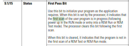
The image at the bottom of this post gives the conditions when S:1/15 will be true for SLC 500, but I do not know what PLC your are using, so you should check the manuals for your PLC to understand when S1:15/1 will be true in your specific situation.


Furthermore, I suggest two things:

  • Document with a comment what you did and why you did it with the First Past bit.
  • Keep the Green and Red rungs next to each other, so all logic that drives O:0/1 can be seen and understood at once.
    • In fact, I would even put it all on one rung, to ensure the logic is never separated, like this:
Code:
          Green       O:0/1
---+-------] [---------(L)---+---
   |                         |
   |       Red        O:0/1  |
   +---+---] [---+-----(U)---+
       |         |
       |  S:1/15 |
       +---] [---+
Alternate approach 1


Here is an alternate, but less certain, approach, which may not work in your situation:


Code:
      Green             B3:0/0
 ------] [---------------(L)---


       Red              B3:0/0
-------] [---------------(U)---


      B3:0/0            0:0/1

-------] [---------------( )---
This takes advantage of the fact that A-B PLCs execute a "prescan" even before the "First Pass" scan, during which many things happen, but the relevant point here is that any bit controlled by an OTE will be set false.


The problem here is if your B3:0/0 bit is ever accidentally set to 1 in your stored program in RSLogix 500, then it will be downloaded as 1 and will turn on O:0/0 on the first pass after power up. Also, if the program is ever switched to REM Program while B3:0/0 is 1, and then switched back to REM Run, then B3:0/0 will still be 1, and O:0/0 will be set to 1 on the first scan, assuming the Red button is not being held down.


In both of those cases - [Power Up] and [REM Program => REM Run], the First Pass method above will work.


Alternate approach 2


This is another was to solve the program using Prescan, but it should not be used; it is only shown here to more fully describe the logic of a Prescan:


Code:
  O:0/1

 ---( )---
This will ensure that the Prescan sets O:0/1 to 0, even before the First Pass scan.


However, the trick here is to put this single run in a separate Program File by itself that is never called (JSR) by any rung in the rest of the program.


There are at least two reasons to not do this:

  • It involves a trick, so your successor, who may not understand that trick or the reason it is there, will wonder why it is there and may remove it
  • The OR branch S:1/15 is much simpler,


From: https://literature.rockwellautomation.com/idc/groups/literature/documents/rm/1747-rm001_-en-p.pdf
xxx.png
 
Another approach.
Have a subroutine that is only called on first scan. Move zero to all you output words.
Zero all timers and counters. Reset any other values that need to be reset before going to run.

Have all other subroutines not be called during first scan.
This ensures your machine/process starts each time from a known state.
 
This is unrelated to the First Pass issue, but you may want to also do something like this:


Code:
      Green  Red      O:0/1

---+---] [---]/[---+---(L)---
on the Green branch, to handle the case when both buttons are pressed, so Red button "wins" the debate, although placing the Red branch after the Green branch will take care of that logically, in the real world it is possible that O:0:1 could be turned on very briefly (one scan) if the PLC I/O is asynchronous with the ladder program scan.
 
Last edited:
Another approach.
Have a subroutine that is only called on first scan. Move zero to all you output words.
Zero all timers and counters. Reset any other values that need to be reset before going to run.

Have all other subroutines not be called during first scan.
This ensures your machine/process starts each time from a known state.


^^^This is a very very good idea.


And if you do it, you should add comments on the Red/Green branches stating that it has been done, again so that all logic concerning O:0/1 can be found in one place.
 
Thank you a lots for your help. I putting a branch around my red button and in the branch put a NO S2:1/15 and this method work successfully.

Best regards.
 
That's something I did not know AB have retentive outputs, how dangerous is that (I must admit I have never tried it on AB). Most PLC's I have worked on will reset a latched output when power loss or the processor is put into stop (for safety reasons), The only time on most systems the latch will stay on is if the logic is true when going into run.
In saying that I never latch real I/O outputs and always use either use the first scan bit or some start up organisation block to set a "Hold" bit which is in every output logic. so on a PLC re-start, it does not interrupt the program flow but will not continue until resumed by the operator. Of course it depends on the process to what I do but under no circumstances do I allow outputs to energise on power up or from stop to run.


I will try to put this to bed.

In the A-B world ALL data is "retentive", and the controller or processor will power up (assuming the backup battery did its job) with all data values as they were when the power went off.

However, in order to resume your logic in a safe way, the controller will perform a "Pre-Scan".

In that pre-scan, the controller will do a once-only scan of the user's program, ignoring any conditionals on each rung, and it will reset all data referenced by "non-retentive" instructions back to default start values.

The intention is that the first "real" scan of the logic sets the appropriate bits to the correct state for the current context of the inputs and internal tags driving those "output" bits.

But it goes deeper than just bits, and you really need to look in instruction help to see what pre-scan does, or might not do for any other instructions...
 
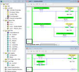
See the image of the program below for an example of what daba is talking about.

Say that PLC mode is [Run], and [The output] (O:0/0) has been latched to 1.

If the PLC mode is then switched from [Run] to [Program], then [The output] will go to 0 while in [Program].

It will also stay 0 when the mode is switched back to [Run], because during pre-scan the OTE on Rung 0 of the bottom routine (PRESCN_ONLY; Program file LAD3) is processed, resulting in that OTE being treated as if its input rung were false, even though that routine is never executed at any other time than during pre-scan.


HOWEVER, if that unused [PRESCN_ONLY/LAD-3] file is removed from the program, so only MAINLADDER/LAD-2 is present, then if [The output] was 1 when the PLC mode was switched from [Run] to [Program], then [The output] will be set to 1 when the PLC mode is switched to [Run], i.e it will be set back to the value it had the last time the PLC mode was [Run].

xxx.png
 
My point exactly, I do not have AB, and I never thought about the output image is retentive as I have always written my code to need an operator resume.
The point was (although I could not test it on AB), assuming all memory be it bits/words outputs are retentive, The situation in AB seems if Button A is pressed while in run mode the output is Latched, on power down or stop, then power back up or run then as the output is retentive, the output will resume its last state, however, take Mitsubishi as an example, using the same scenario when the plc is powered down or put into stop & back into run the output will be off as they are non retentive (of course, if the logic setting it is true then yes it will re-latch). On Mitsubishi only certain ranges are retentive, these can be expanded but outputs are not included.
It is not a problem outputs being retentive, however, latching & unlatching outputs I believe should be avoided.
 
Dear drbitboy,

If I have a 100 Latch OTE, then I need to treated all of them in the PRESCN_ONLY Program file LAD3 , this is unreasonable !
 
See the image of the program below for an example of what daba is talking about.

Say that PLC mode is [Run], and [The output] (O:0/0) has been latched to 1.

If the PLC mode is then switched from [Run] to [Program], then [The output] will go to 0 while in [Program].

It will also stay 0 when the mode is switched back to [Run], because during pre-scan the OTE on Rung 0 of the bottom routine (PRESCN_ONLY; Program file LAD3) is processed, resulting in that OTE being treated as if its input rung were false, even though that routine is never executed at any other time than during pre-scan.


HOWEVER, if that unused [PRESCN_ONLY/LAD-3] file is removed from the program, so only MAINLADDER/LAD-2 is present, then if [The output] was 1 when the PLC mode was switched from [Run] to [Program], then [The output] will be set to 1 when the PLC mode is switched to [Run], i.e it will be set back to the value it had the last time the PLC mode was [Run].

drbitboy, I have highlighted in red above some statements that are inaccurate, and could be misleading.

The output bits in the output data-table do NOT get turned off while you are in program mode, they stay at their last value.

Data transfer to the output module(s) is halted, and it is the output modules themselves that turn the physical outputs off when the controller is not in a [RUN] mode. This is true for all PLC and SLC/Micrologix controllers.

However, Logix5000 series output modules are capable of being configured so that the outputs go off, hold last state, or come on when the controller is not in a [RUN] mode. Similarly if the output module loses communication with the controller. All of that configuration is per bit, not the whole module.

EDIT : You appear to be confused between Pre-Scan, and First-Scan.

Pre-Scan is NOT a routine you can program code for. It is an entirely automatic scan of the user code, prior to going into [RUN] mode, during which all Non-Retentive data is reset to default states. Bits referenced by OTE's are rest to zero, Timers (TON and TOF) are reset, File handling Instructions are reset, One-Shot storage bits are turned ON. Pre-Scan is triggered by the controller attempting to go into [RUN] mode, whether that is by a mode-change [PROG] to [RUN], or the controller re-starting after a power-down. During the Pre-Scan, no code is actually executed, it is just "scanned", and the resetting of non-retentive data takes place.

First-Scan is simply a status bit you can look at, and do anything you want with it. You could call a subroutine to "initialise" things. You could set an alarm bit so you know the controller has been re-started. Or you could use that bit to place all running sequences into a "Hold" state, nothing should re-start automatically, unless it is imperative to do so, an example may be forced ventilation fans for instance.
 
Last edited:
Dear drbitboy,

If I have a 100 Latch OTE, then I need to treated all of them in the PRESCN_ONLY Program file LAD3 , this is unreasonable !

Then don't do it....

Firstly, there is no program file associated with the Pre-Scan, it is an entirely automatic process triggered by the controller entering into [RUN] mode. There is NO "pre-scan" status bit you can look at, and you cannot run any code during it.

Write your code so that only the bits you want to retain last value do so (i.e. use OTL/OTU), and the bits that you don't want to retain will get turned off by the pre-scan (use "seal-in" logic to drive an OTE).

The technique of setting/unsetting bits by calling a subroutine once, happens on the "First Scan", which you can determine by looking at the First Scan status bit.
 
Last edited:
I tend to agree with Dabba, although in Mitsubishi because the Output table (not physical outputs) is non retentive, all bits will be set to off, this probably happens on start or pre scan if you want to call it that. Like I said in that platform only memory that has been set to retentive will retain it's state all others will default back to 0. or false and outputs are not included in the retentive settings. So if an output is latched but the logic that sets it is false at the time it re-starts it will not keep it's latch status, any rung that is true will latch or turn on an output at the end of first scan when the output table is updated.
I believe this is true on Siemens, the data that is retained is Data blocks not flags/markers (not too sure about the latest S7). I also believe that on Mitsi the internal data tables are not uploaded by default whereas it seems on AB they are. (correct me if I'm wrong on AB)
 

Similar Topics

Hello all. I have been working with an SLC 5/04 system, which houses various Digital and Analog INs and OUTs, up to Slot 29. I am currently...
Replies
3
Views
2,502
Hi friends i want to know how first scan bit is used in rslogix 5000 if i use the emulator? is it possible that use the module fault bit as well...
Replies
2
Views
7,963
Hello. Does anyone know the equivalent of the first scan bit in a L32ER compactlogix? Do o need to obtain it via GSV? I’m looking to regain...
Replies
3
Views
440
I want to know how to make a flip flop rung that will change states every scan. This is for a fast sequencer. Is there a special bit similar to a...
Replies
8
Views
2,175
hello all, I am trying to set up a latch bit like this S:FS----- true condition------OTL. I tried in rs emulator and it the bit latches but in...
Replies
13
Views
1,827
Back
Top Bottom