Logix Designer

miller20

Member
Join Date
Jan 2020
Location
michigan
Posts
41
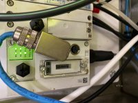
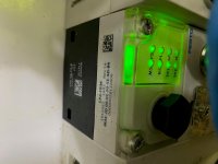
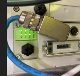
Hi guys hope everyone is doing well looking for some help on studio5000 logix designer. I have a system at my plant its fairly new as i am fairly new to logix designer, i am trying to figure out how can i see what valve numbers they are using in the program? I can find no indication to which pneumatic valve does what i attached a picture below maybe someone could help me out.

TIA

BE SAFE

TECHNIBLEND PNU VALVES.jpg TECHNIBLEND PNU VALVES 2.jpg TECHNIBLEND PNU VALVES 1.jpg
 
Thanks for those photos !

The Fest CPX-FB36 is their 2-port EtherNet/IP adapter for the CPX I/O and valve manifold system. The data maps can be very complex because CPX is so flexible with the variety of I/O modules, regulators, and valves that can be assembled and connected.

Even though my company uses these extensively, I always have to poke values into the I/O tags to help myself correlate the tag addresses with the actual valves.

Because this is a system that's already working, you can use the existing program and configurations and improve their documentation and comments.

First, figure out the IP address of that CPX-FB36 adapter. Maybe it's labeled on the cable, or in a drawing, or you know which one of the objects in your Studio 5000 project I/O tree matches it.

Open up that IP address in a Web browser and take some notes about the configuration and modules that are displayed there.

And download the Festo Maintenance Tool (FMT) from the Festo support portal. It will allow your computer to connect and upload the configuration of the module and allow you some access and monitoring in addition to what's in the Web Browser interface.

With just two outputs on in the Output tag associated with the Generic Ethernet Module in Studio 5000 for that CPX-FB36, you should be able to figure out which of the bits in the Output:Data[x].y tag are associated with which valved. Generally bits 0,1 are that first valve, bits 2,3 are the second valve, and so on.
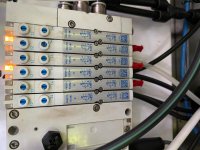
 
Watch out for this cable

A little bit off your topic but perhaps relevant for this system you are looking at, may I advise you to look into this Ethernet cable? I would consider finding a way to have it connected to the device without the stress it seems it is under. You are not using the other port, are you? Maybe if you connect the cable on the other port it may be subject to less stress. Or maybe this cable has been rolled in the cabinet and you may be able to unroll some 20 cms or so, so as not having the cable the way it seems to be with the picture. Cables under stress can bring problems down the read, especially cables made on-site. Just a thought.hope this helps.

LAN_CAble.png
 

Similar Topics

How do I organize the template for my controls. I am new to Logix Designer but have used RS500 and RS5000. My new Logix Designer has Toolbars...
Replies
8
Views
191
Hello, Im building project with 1756-L82ES controller and 1756-IB16S card but i cant find it when trying to add the card to IO configuration...
Replies
3
Views
117
Does anyone know how to set the background colors of instuction blocks (TON, MOV, etc)?
Replies
1
Views
121
Hello all, I'm trying to use the Logix Designer SDK to upload and download a single ACD to many controllers. I got this to work fine copying...
Replies
0
Views
60
Hello, I am trying to connect a Stride Analog Output module to a 1769 CompactLogix via Ethernet. I added a new Generic Ethernet Module for the...
Replies
4
Views
222
Back
Top Bottom