You are using an out of date browser. It may not display this or other websites correctly.
You should upgrade or use an alternative browser.
You should upgrade or use an alternative browser.
Siemens S7 Assembly Language?
- Thread starter Wolan
- Start date
cardosocea
Member
Which bit of that? the P#L20.0? Or the call to SFC64? Silly question, what is SFC64?
Two reasons.Odd that Jesper hasn't mentioned this, but if you create a Rung/Network in Ladder and then press Ctrl+1/2/3, it will change the display of the logic into FBD and STL.
1. I dont want to be lured into teaching STEP7 Classic step by step. I assume that people can read the manuals and try out stuff by themselves. Swithing between views can also be done via the menu without knowing the shortcuts.
2. The code does not look like it can be switched to LAD or FBD. All the LAR2 and TAR2 is typical of SCL. And the absence of the BLD's and that it looks like one huge network.
Good tip. This will tell you what was the original programming language.JRW said:Look at the blocks folder FB514 , you can see what programming language the code was originally written in
Like I said before:
If this is a large program with SCL or GRAPH code, then even I could not reverse engineer it.JesperMP said:Reverse engineering an uploaded S7 program without comments or symbols is a really tall order. If one thinks one can just go online to troubleshoot an S7 program without the source code will find it a seriously tough job. And since this is a top of the line 319 CPU, the program is probably not tiny at all.
If it is just a small program with LAD code and 3-4 conditions turning on an output, then it is possible. But this is not the case.
Even that takes some know how. But being able to read out hardware diagnostics and the diagnostics buffer is really valuable for troubleshooting the hardware.JesperMP said:You can probably troubleshoot hardware problems though.
L D[AR2P#0.0]
Lifetime Supporting Member
Which bit of that? the P#L20.0? Or the call to SFC64? Silly question, what is SFC64?
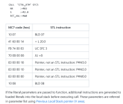
The combination of the UC and the list of parameters that follow it is the 'native' code behind the editor view. SFC64 reads the system clock. All FC 'calls' are implemented in this way i.e. there is no S7 opcode for call, only UC/CC
To answer some of the questions...
Yep this is originally written in SCL per the properties of the blocks.
This seems like a large program and there is no I/O listed. It looks like it is all remote I/O through profibus.
And as I learned there is no symbols ether due to lack of listed I/O and me pulling the program from the PLC.
Thanks for the great info so far!
It helps!

The combination of the UC and the list of parameters that follow it is the 'native' code behind the editor view. SFC64 reads the system clock. All FC 'calls' are implemented in this way i.e. there is no S7 opcode for call, only UC/CC
Sometimes the Step7 Editor switches back to the MC7 view even in blocks original written in STL. For example if the call parameters doesn't match the parameters of the block of a called function in the block folder, so the editor can't build the STL code back from MC7 code.
Also Step7 has a hidden feature to activate the MC7 view, but it's unlikely that it happens accidentally.
As far as I know there is no way to display the MC 7 instruction set, only STL the MC7 instuctions can only be viewed in a hex editor by loading them directly from disk.
the MC7 code for UC is
HEX FB 74 XX XX UC XXXX (SFC1 .. SFC65535)
The MC 7 code is displayed as STL or FBD or Lad or whatever, many of the codes (used for either layout i.e. treated as NOP in the PLC) are not actually code the PLC uses purely for the display mode.
Here are a few others.
00 92 XX XX AN I XXXX.2 (I128.2 .. I65535.2)
00 93 XX XX AN I XXXX.3 (I128.3 .. I65535.3)
00 94 XX XX AN I XXXX.4 (I128.4 .. I65535.4)
00 95 XX XX AN I XXXX.5 (I128.5 .. I65535.5)
00 96 XX XX AN I XXXX.6 (I128.6 .. I65535.6)
00 97 XX XX AN I XXXX.7 (I128.7 .. I65535.7)
00 A0 XX XX AN Q XXXX.0 (Q128.0 .. Q65535.0)
00 A1 XX XX AN Q XXXX.1 (Q128.1 .. Q65535.1)
00 A2 XX XX AN Q XXXX.2 (Q128.2 .. Q65535.2)
00 A3 XX XX AN Q XXXX.3 (Q128.3 .. Q65535.3)
00 A4 XX XX AN Q XXXX.4 (Q128.4 .. Q65535.4)
FB & SFB calls
When CALL FBx instruction is entered in the STL editor, the additional instructions are generated which copy parameters passed to FB into the instance data block.
For example,
CALL FB 1,DB1
in1:=TRUE
in2:=MB10
out1:=M10.0
out2:=MW12
io1:=MD14
the following FB1 code:
SET
A #in1
NOT
= #out1
L #io1
L #in2
+I
T #out2
T #stat_stat
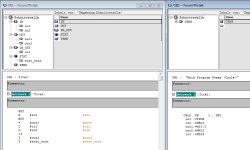
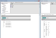
The call is translated into MC7 code as follows:
MC7 code (hex) (STL instruction)
10 03 (BLD 3)
41 60 00 18 (= L24.0)
FB 7C (CDB)
FB 79 00 01 (OPN DI1)
FE 6F 00 14 (TAR2 LD20)
68 1D (SET)
41 50 00 00 (=DIX 0.0)
0A 0A (L MB10)
7E 55 00 01 (T DIB 1)
1A 0E (L MD14)
7E 57 00 06 (T DID6)
FE 0B 84 00 00 00 (LAR2 P#DB0)
75 01 (UC FB1)
FE 6B 00 14 (LAR2 LD20)
00 50 00 02 (A DIX 2.0)
98 0A (=M10.0)
7E 52 00 04 (L DIW4)
13 0C (T MW12)
7E 53 00 06 (L DIB6)
1B 0E (T MD14)
FB 7C (CDB)
10 04 (BLD 4)
The FB1 is translated into MC7 code as follows:
MC7 code (hex) STL instruction
68 1D (SET)
79 58 00 00 (A DIX [AR2, P#0.0])
68 2D (NOT)
79 DA 00 10 (= DIX [AR2,P#2.0])
BE 5B 00 30 (L DID [AR2, P#6.0])
BE 59 00 08 (L DIB [AR2, P#1.0])
79 00 (+I)
BE 5E 00 20 (T DIW [AR2, P#4.0])
BE 5F 00 50 T DID [AR2, P#10.0]
janner_10
Lifetime Supporting Member
Out of interest, what are you doing to the machine?
New PLC?, adding things etc?
New PLC?, adding things etc?
That is not MC7, MC7 is pure Hex codes, this is interpreted by the IDE as per your screenshots the actual MC7 code is what is downloaded to the PLC.
It was the same with S5.
MC7 is the lowest level of the assembly language. If you write x86 assembler code, you write a text in x86 assembly language. There is a direct representation of hex-values to a MC7 code, but you can't write all MC7 codes in STL, like parameter passing.
I think you mis-understand what I was posting (or perhaps I mis-understood you).
You cannot view MC7 in the IDE this is purely what is downloaded or uploaded to the IDE & file, the IDE interprets the MC7 code into a sort of assembly language and vice versa, there is a way of using MC7 directly (well certainly in S5 as I worked with an engineer who originally worked for Siemens in Germany.
To actually execute an MC 5 (or possibly MC7) as I'm not sure you can in S7, you can load the hex value of an instruction into a flag word or DW, process the instruction which will run the code.
Cannot remember exactly how it was done but the engineer I worked with showed me it was a way of running code that changes (very dangerous) but worked.
For example; create a datablock & put in the hex MC5 code in the words in an FB use a system instruction (cannot remember which) but you loaded the DW with the MC5 hex code, process a system instruction that ran the MC5 instruction.
For example (not a real one as I cannot remember exactly how it is done)
C DB 10 //Call the DB
L KH 83A081 T DW 10 // Load the MC5 hex code into DW10
xxxxxx // Process the DW with a system instruction i.e. run the instruction
Now
if you change the MC5 hex value on the next scan it would change the instruction. seen it running so in effect, code that modifies it'self.
There were things I learned that I did not know existed, one was where a datablock was created on the fly (normally simple i.e. in a startup OB generate the datablock), however, in this one application the engineer wanted a DB as big as possible for a printer buffer, so in the warm startup OB, there was a check on spare ram after program loaded, generated the DB to take up virtually all spare memory, this was a problem though, if for some reason the program was lost, if someone had taken an upload of the program & tried to download it, it failed on out of memory.
You had to delete or not download the DB, do something like cold re-start, then a warm restart via the PG, once generated, you could not make changes to the program as the memory was full, S5 (and probably S7) requires spare memory large enough to be able to download a block, the system does not overrite the existing block but puts it into spare ram, remove the header in the table for the old block then replace it with the new pointer to the updated block, originally in S5 after so many downloads of blocks you had to compress the memory as it would fill up (i.e. did not remove the old block) this was changed on later versions where every time a block was downloaded it compressed the memory i.e. got rid of the old blocks.
Also see the MC7 code for a block call with passing of parameters below.

Similar Topics
I just received a piece of equipment with a Siemens 3LD2254-0TK53 mains switch (see attached picture). I can't access the incoming power terminals...
- Replies
- 4
- Views
- 1,759
Hey everybody,
I've recently started messing around with TIA portal V11. Reviewing my company's software. A lot of it was written in poorly...
- Replies
- 6
- Views
- 7,345
Hello
I have a s7-1200 and I would like to read the tags present in this controller with my controllogix controller. The two controllers don't use...
- Replies
- 3
- Views
- 37
Hi need help why this “failure 5 emergency stop “ appears at every startup in the morning ?
Have to shut off main switch at least 10 times on...
- Replies
- 19
- Views
- 254
i have two plc
1. s7-1212dc/dc/dc ip; 192.168.0.1
2. s7-1500 1513-1pn ip; 192.168.3.2
i need to get data from plc1 to plc2. any idea how to do...
- Replies
- 5
- Views
- 90


