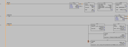
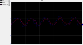
I've become interested in code for digital filtering. I have read this excellent (and old) thread : http://www.plctalk.net/qanda/showthread.php?t=43380 and decided to try my luck with a Butterworth filter (zipped AOI attached).
I very briefly learned about digital filtering in school, where we learned about first order filters. I programmed one of these on the fly as well to compare. It seems that for equivalent lag time, the Butterworth filter follows more closely the original, non-distorted sine wave (see trend and sim ladder - I could have been more aggressive but eh, those are just tests). Now, the problem I'm having is that I don't really know how any of it works. I have a few questions :
- does the AOI code looks right?
- are those result representative of the performance differences between this implementation of the Butterworth and a "standard" (I used Rockwell's formula) low pass first order filter? From the tread, it seems a second order filter attenuates more aggressively undesired frequencies.
- in school I was told that sample time ought to be at least period/20 (ie. 20 samples or so) to ensure a realistic representation of the filtered signal. Does that still hold in second order filters, and/or is there a better way of choosing the value? I do sample at the same rate as my filter's sample time, right?
- how do I choose the cutoff frequency? In the thread it does say it should be about 10 times lower than the sample time. I vaguely remember the term from electronics, but what about when I'm just filtering a number? Do I just wing it until I find something tolerable (in this case I winged it)? What would be a better, more precise way?
Sorry if those are dummy questions, I'm still in school and still learning (and I expect I'll always be).
Thanks!


